Flight Director Attitude Indicator (CSM)

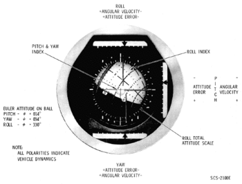
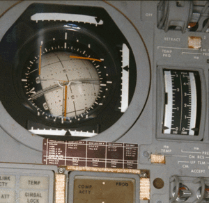
The Flight Director Attitude Indicator (FDAI) is used to display various attitude informations of the spacecraft, similar to a artificial horizon of an aircraft. The FDAIs provide displays to the crew of angular velocity (rate), attitude error with respect to a defined other attitude, and total attitude. One or both FDAIs are turned on or off with the FDAI/GPI POWER selection switch on panel 7I.
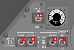
The full-scale deflection ranges of the angular velocity (attitude rate) scale and the attitude error scale can be adjusted with the FDAI SCALE switch B: If the switch is in ERR/RATE 5/1 position, full scale on the attitude error indicators is 5° and full scale of the rate indicators is 1° per second. If the switch is in ERR/RATE 5/5 position, full scale on the attitude error indicators is 5° and full scale of the rate indicators is 5° per second. In the ERR/RATE is 50/15 50/10, full scale on roll error is 50° and on roll rate is 50° per second, the full-scale deflection of the pitch and yaw error is 15° and the full-scale deflection of the pitch and yaw rate is 10° per second.
FDAI display modes

The following tableAOH explains what the FDAIs show with the different switch settings. At first the CMC ATT switch A is always switched to IMU, the GDC position is a backup for the CMC attitude, but was never used and so is not explained here. On the left side you see the various settings for the FDAI SEL C, FDAI SRC D and ATT SET switches E, "(any)" means the FDAI readings don't depend on that switch. On the rigth side it is explained what attitude and error the FDAIs show, the following abbreviations are used :
- IMU: Current total attitude indicated by the IMU
- GDC: Current total attitude indicated by the GDC
- (null): No Attitude, FDAI is off.
- CMC: Error needles are controlled by the CMC, readings depend on the CMC program (the DAP for instance).
- BMAG1: If BMAG 1 is uncaged in attitude hold mode (ATT1/RATE2 mode) the error needles show the difference between the GDC attitude and the BMAG 1 attitude.
- IMU/ASCP: The error needles show the difference between the IMU attitude and the attitude currently set in the ASCP.
- GDC/ASCP: The error needles show the difference between the GDC attitude and the attitude currently set in the ASCP.
| Switch Settings | FDAI 1 | FDAI 2 | ||||
|---|---|---|---|---|---|---|
| FDAI SEL | FDAI SRC | ATT SET | Attitude | Error | Attitude | Error |
| 1/2 | (any) | (any) | IMU | CMC | GDC | BMAG1 |
| 1 | CMC | (any) | IMU | CMC | (null) | (null) |
| 1 | GDC | (any) | GDC | BMAG1 | (null) | (null) |
| 1 | ATT SET | IMU | IMU | IMU/ASCP | (null) | (null) |
| 1 | ATT SET | GDC | GDC | GDC/ASCP | (null) | (null) |
| 2 | CMC | (any) | (null) | (null) | IMU | CMC |
| 2 | GDC | (any) | (null) | (null) | GDC | BMAG1 |
| 2 | ATT SET | IMU | (null) | (null) | IMU | IMU/ASCP |
| 2 | ATT SET | GDC | (null) | (null) | GDC | GDC/ASCP |
A pilot's view of the FDAI
Christophe, a pilot by profession, explains the FDAI (and the ORDEAL) like this:
"I'm a pilot and what is very disturbing for pilots is that we understand the FDAI as an artificial horizon similar to those we know in aircraft. But in fact, although the Apollo FDAI has the same purpose than a classic horizon (to display the attitude) the goal, the operation and above all the reference are quite different.

First, you have to consider that the system is composed of 2 FDAI that are identical and of 2 subsystems for giving the reference: The main one is the Inertial Measurement Unit (IMU) which could be summarized as an inertial platform. The second and backup one is Gyro Display Coupler (GDC) using BMAGs which are body mounted attitude gyros. Both of the FDAI could be coupled either on the IMU or on the GDC while the standard mode is FDAI 1/IMU and FDAI2/GDC.
Second, depending on which phase of the mission you are, the display you need is not always the same. And while a spacecraft is not really flying above the surface like an aircraft does, but is orbiting around a planet, the "zero reference" (I mean that you read "pitch 0°", "bank 0°" and "ball centered") is not necessary when the spacecraft is nose on the horizon, "wings" at level and pointing toward the heading.
However, astronauts of the days of Apollo were mainly pilots and wanted to have some displays as close as they used to see on an airplane flying in atmosphere. So they used two main different mode of display:
The first one is called "Inertial Stellar". That means that the reference is a 3D system of coordinates which is fix relative to the stars. That does not mean that there's only one system of reference. In fact, there is a system of reference for almost every phase of the mission. Some are reused during the flight and. in order to be accessed multiple times, they are stored in the computer as "REFSMMAT", which stands for REference For Stable Member Matrix. If you use the Virtual AGC, you can activate those REFSMMAT while doing IMU realignment Program P52 or P54 (option 3 "REFSMMAT").
Others are used only once for specific maneuvers, in fact there are unique ones for individual burns. These are computed in real time by the computer while in thrust programs (P40's) and can be activated by the P52 or P54 programs (option 1 "preferred"). The purpose of the burn specific reference frames is to display the zero reference (corresponding to 'wings' at level and "ball centered" in an aircraft) or when the spacecraft is steady at the desired burn attitude. In this case, if there is something wrong with the autopilot when the burn as started and the spacraft commence to drift in a wrong attitude, it's more easy for the astronaut to manually control the ship and return it to the right attitude corresponding with the 0° deflection from each axis.
There are other specific systems of reference for attitude, like "lunar landing" for example.
You understand easily that, if the reference is fixed relative to the stars, the display will be fixed too. So if, for example, your spacecraft is orbiting around the earth and for some reason you want to orient it in a fix attitude relative TO THE EARTH SURFACE (this is what you would call "surface relative" in Orbiter terms) because you want to turn the window and maintain its orientation toward the ground to take some snap-shots. In this mode the FDAI will rotate slightly as you are orbiting, because it is fixed to the Earth while "you" (the ship) are not. This is something which is not an issue to the scientists and engineers, where the math works out the same, but that is totally unacceptable for pilots, such as the astronauts who "think with their guts", and require a frame of reference that they makes them comfortable. That the reason why NASA developed a second mode of display: the ORDEAL.
ORDEAL means "Orbital Rate Display Earth And Lunar" or "Orbit Rate Drive Electronics for Apollo and LM", both definitions appear in the documentation. It's an additional instrument box installed near the left hand window inside the command module. This box can set the coupled FDAI to automatically rotate around the pitch axis at the same rate of the orbital period. This means that, while the ship is orbiting around the Earth (or Moon) and rotating itself in order to maintain the same side toward the surface, the ORDEAL FDAI displays a FIXED reference attitude. Almost exactly as if you were sitting in a aircraft flying in the atmosphere. According to the historical Apollo flight plans, the Ordeal mode was the standard one used while orbiting around Earth or Moon, except for during the burns and rendezvous maneuvers.
To conclude, let us consider the other displays you can find on the FDAI:
Errors needles: The yellow ones accross the ball that are like cross bar of a Flight director : they have the same purposes and are of "go to" type. But take care and pay attention to the source they come from!
Rate needles: the little triangles near the balls that indicates the rotating rates of the spacecraft.
<biblio force=false>
- References
- SPACE1 http://www.space1.com
- I FDAI 1 receives DC power from the SCS SYSTEM MNA circuit breaker and AC power from the STAB CONT SYSTEM AC1 circuit breaker on panel 8. FDAI 2 receives DC power from the SCS SYSTEM MNB circuit breaker and AC power from the STAB CONT SYSTEM AC2 circuit breaker.
</biblio>