Rotation Hand Controller
The Rotation Hand Controller (RHC) provides the capability of manual control of spacecraft rotation in either direction about each axis. Also the RHC may be used for manual thrust vector control (see SPS). In the real CSM there were two identical Rotation Hand Controllers, in Project Apollo - NASSP both are simulated simultaneously by using one joystick or Orbiter's attitude controls (joystick, keyboard) as configured with the Launchpad Configuration Options.
Quickstart Mode
In Quickstart Mode the RHC isn't used, but the CSM RCS and the SPS engine are controlled by Orbiter directly as for example in the Delta-glider including the navmodes (killrot etc.), attitude and engine control by MFDs etc. So this article applies in Virtual AGC Mode only, but optionally Orbiter attitude control can be disabled with the Launchpad Configuration Options for Quickstart Mode, too.
RHC commands

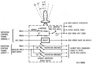
The axes of the real RHC are the same as the axes of of a typical 3-axes joystick, so if a joystick is configured it can be used as usual. In case of Orbiter's attitude controls they are used as configured in Orbiter. Within the RHC there are three command sources per axis:
- Breakout Switches - A switch closure occurs whenever the RHC is moved 1.5° from its null position (about 12% of total deflection). Separate switches are provided in each axis and for each direction of rotation. These six breakout switches are used to provide: command signals to the CMC, SCS minimum impulse and acceleration commands, BMAG cage signals and proportional rate command enabling.
- Transducers - Transducers produce AC signals proportional to the RHC displacement from the null position. These signals are used to command spacecraft rotation rates during SCS proportional rate mode and to command SPS engine gimbal position during Manual Thrust Vector Control (MTVC).
- Direct Switches - Direct switches will close whenever the RHC is moved a nominal 11.5° from its null position (about 92% of total deflection). Direct switch closure will produce acceleration commands through the RCS direct solenoids.
Power supply

An RHC needs to be powered before it can be used, of course. Since the simulated RHC is both RHC 1 and 2, the simulated RHC is working if one or both RHCs are powered. The power for the direct switches and direct RCS thruster solenoids is independant of the normal power supply.
Normal power
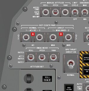
The RHC breakout switches are powered with DC power if one or both of the ROT CONTR PWR NORMAL 1 or 2 switches A are switched to AC/DCI. The transducers are powered with AC power if one or both of the ROT CONTR PWR NORMAL 1 or 2 switches A are switched to AC/DC or ACII.
Direct power
The RHC direct switches are powered with DC power if one or both of the ROT CONTR PWR DIRECT 1 or 2 switches B are switched to MNA/MNB or the ROT CONTR PWR DIRECT 1 switch is switched to MNA or the ROT CONTR PWR DIRECT 2 switch is switched to MNBIII.
<biblio force=false>
#I The ROT CONTR PWR NORMAL switches receive DC power from both the SCS CONTR/AUTO MNA and MNB circuit breakers on panel 8.
#II The ROT CONTR PWR NORMAL 1 switch receives AC power from the SCS AC1 circuit breakers on panel 8, the ROT CONTR PWR NORMAL 2 switch receives AC power from the SCS ECA/TVC AC2 circuit breakers on panel 8. For both switches the ECA needs to be powered, too.
#III The ROT CONTR PWR DIRECT 1 switch receives DC power from either both the SCS CONTR/DIRECT 1 MNA and MNB circuit breakers on panel 8 when switched to MNA/MNB or from the SCS CONTR/DIRECT 1 MNA circuit breaker on panel 8 only when switched to MNA. The ROT CONTR PWR DIRECT 2 switch receives DC power from either both the SCS CONTR/DIRECT 2 MNA and MNB circuit breakers on panel 8 when switched to MNA/MNB or from the SCS CONTR/DIRECT 2 MNB circuit breaker on panel 8 only when switched to MNB.
#References
</biblio>