Service Propulsion System: Difference between revisions
imported>Tschachim |
imported>Swatch |
||
| Line 41: | Line 41: | ||
[[Image:SPS_switch_location_1.jpg|thumb|180px|right|Location of SPS displays & controls on panel 3, upper part {{Panel label|name=3}}]] | [[Image:SPS_switch_location_1.jpg|thumb|180px|right|Location of SPS displays & controls on panel 3, upper part {{Panel label|name=3}}]] | ||
During a burn the fuel and oxidizer in the tanks are pressurized with helium to about 175psi in order to press the propellants through the | During a burn the fuel and oxidizer in the tanks are pressurized with helium to about 175psi in order to press the propellants through the feed lines to the engine thrust chamber, where they ignite. The fuel and oxidizer tank pressure is shown by the SPS PRPLNT PRESS meters {{Panel label|name=3.C}}. The helium used for that is stored in the helium tanks, which pressure {{Panel label|name=3.B}} can be monitored by switching the SPS-PRESS IND switch {{Panel label|name=3.M}} to He. The fuel and oxidizer tanks are pressurized with the helium pressure regulator assemblies if one if the two SPS helium valves A/B are open. The helium valves are continuous-duty solenoid-operated and are energized open and spring-loaded closed. The SPS He VLV A/B switches {{Panel label|name=3.K}} permit automatic or manual control of the valves<cite>II</cite>. With the switch in the AUTO position, the valves are automatically controlled by the thrust on/off signal, which is the default switch position. The valves are controlled manually by placing the switches to the ON (valve open) or OFF (valve closed) positions. Each valve position is shown by a talk-back indicator {{Panel label|name=3.K}} above each switch. When a valve is closed, the corresponding indicator is barber-pole(diagonal lines), the indication during non-SPS thrusting periods. When a valve is open, the the corresponding indicator is grey, the indication during SPS thrusting periods. | ||
The propellant pressurization can be tested with following procedure: | The propellant pressurization can be tested with following procedure: | ||
Revision as of 05:06, 20 November 2006

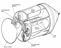
The Service Propulsion System (SPS) is the Command/Service Module main engine and provides the impulse for all velocity changes (ΔVs) throughout a mission and the SPS abort capability after the launch escape tower is jettisoned. The engine uses Aerozine 50 (hydrazine/UDMH) fuel and nitrogen tetroxide oxidizer and has a maximum thrust of 20,500 lbf (91.2 kN). This hypergolic fuel combination is pressurized with helium during thrusting periods, so no propellant pump is needed. The propellant flow from the tanks to the thrust chamber is controlled by the engine injector valves, which are pneumatically controlled with nitrogen. The engine is gimbaled to allow thrust vector control during a burn.
Quickstart mode
In Quickstart mode the SPS engine works like a normal Orbiter main thruster. The engine can be throttled with the keyboard or Orbiter's joystick control as usual, although the real SPS engine isn't throttleable. The Interplanetary MFD (IMFD) autoburn program can be used, too. It's not necessary to use the panel displays and controls, the Orbiter engine displays can be used though the panel displays are enabled normally.
Engine thrust on/off logic

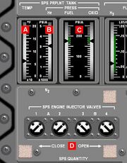
In Standard mode and Virtual AGC mode the SPS engine works like the real thing, that means as specified in the original documentationAOH. So the real SPS engine isn't throttleable, it only can be turned on or off by opening or closing one or both of the two pairs of engine injector valves (bipropellant valve systems A or B) 3.D pneumatically. The gaseous nitrogen pressure of valve system A and B 3.B can be monitored by switching the SPS-PRESS IND switch 3.M to N2 A or N2 B.
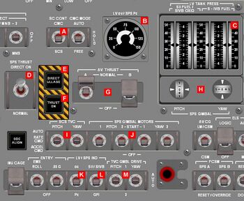
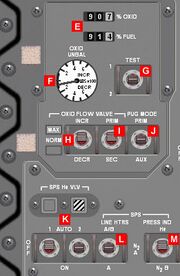
In order to fire the SPS engine, the ΔV THRUST A and/or ΔV THRUST B switches 1.G are unguarded and switched to NORMAL ("single/double bank operation") to arm the control logic for engine injector valve system A or B.I During a burn the SPS chamber pressure can be monitored with the LVα/SPS Pc indicator 1.B, when the LV/SPS IND switch 1.K is placed to Pc. Normal chamber pressure is 100psi. The remaining fuel and oxidizer quantity percentage in the tanks is shown by the corresponding indicator 3.E.
Now there are 3 ways or thrust modes to fire the engine:
SPS thrust direct on mode
The SPS engine is designed to be very reliable, so the easiest way to fire the engine, just in case everything else failed, is to switch the SPS THRUST switch 1.D to DIRECT ON. It can be stopped again by switching back to NORMAL.
CMC ΔV mode
The normal way to control the SPS engine is to use the Command Module Computer (CMC). The Virtual AGC uses program P40 to both provide the thrust on signal and to control the SPS thrust vector. The C AGC has a couple of fictional programs to support the different mission phases. For both CMC versions the SC CONT switch 1.A is switched to CMC.
SCS ΔV mode
Thrust vector control
In order to control a ΔV manoeuver the SPS engine can be gimbaled and change it's pitch and yaw gimbal angles to provide thrust vector control. Currently only the Virtual AGC does thrust vector control.
The current SPS gimbal angles can be montitored by using the LV TANK PRESS/SPS GIMBAL meter 1.C, the -5°/+5° scale is used, provided that the LV/SPS IND switch 1.L is in GPI position.
Propellant pressurization

During a burn the fuel and oxidizer in the tanks are pressurized with helium to about 175psi in order to press the propellants through the feed lines to the engine thrust chamber, where they ignite. The fuel and oxidizer tank pressure is shown by the SPS PRPLNT PRESS meters 3.C. The helium used for that is stored in the helium tanks, which pressure 3.B can be monitored by switching the SPS-PRESS IND switch 3.M to He. The fuel and oxidizer tanks are pressurized with the helium pressure regulator assemblies if one if the two SPS helium valves A/B are open. The helium valves are continuous-duty solenoid-operated and are energized open and spring-loaded closed. The SPS He VLV A/B switches 3.K permit automatic or manual control of the valvesII. With the switch in the AUTO position, the valves are automatically controlled by the thrust on/off signal, which is the default switch position. The valves are controlled manually by placing the switches to the ON (valve open) or OFF (valve closed) positions. Each valve position is shown by a talk-back indicator 3.K above each switch. When a valve is closed, the corresponding indicator is barber-pole(diagonal lines), the indication during non-SPS thrusting periods. When a valve is open, the the corresponding indicator is grey, the indication during SPS thrusting periods.
The propellant pressurization can be tested with following procedure:
- It's assumed the CSM is flying free, has power supply and enough SPS propellants etc. Furthermore the SPS He VLV A/B switches 3.K are still placed to AUTO and the fuel and oxidizer pressure is fine, that means about 175psi.
- Start the SPS engine by switching the ΔV THRUST A switch 1.G to NORMAL and the SPS THRUST switch 1.D to DIRECT ON. The SPS He VLV A/B indicators 3.K change to grey indicating that the valves are opened automatically, the propellant pressures remain constant.
- Switch both SPS He VLV A/B switches 3.K to OFF. The SPS He VLV A/B indicators 3.K change to striped-line indication again indicating that the valves are closed. Depending on the propellant quantity the fuel and oxidizer pressure 3.C begins to decrease. When the tanks are full, the pressures drop rapidly. If the tanks are more empty, the pressures drop more slowly because of the bigger amount of helium in the tanks. Additionally the SPS chamber pressure 1.B begins to decrease and the thrust level decays.
- When the propellant pressure drops below 157psi, the Caution & Warning System triggers the SPS PRESS alarm, press the MASTER ALARM pushbutton/light to turn off the alarm.
- Switch one or both SPS He VLV A/B switches 3.K to AUTO again. The propellant and chamber pressures increase to the normal values and there's full thrust again.
The procedure is not realistic, of course, normally the helium valves operate automatically during the mission.
Propellant utilization & gauging

The Propellant Utilization and Gauging Subsystem (PUGS) provides two important features, it measures the remaining fuel and oxidizer quantities and it displays and controls the fuel/oxidizer mixture ratio. Normal mixture ratio fuel:oxidizer is 1:1.6 and this is the initial propellant ratio in the tanks at the beginning of the mission, too. So when both the fuel and oxidizer quantity meters 3.E indicate the same percentage value, the propellants are balanced, the OXID UNBAL meter 3.F indicates 0lbs unbalance.
Propellant Utilization Valve
If any unbalance exists, which is determined from the INCR, DECR readings on the OXID UNBAL meter 3.F, the propellant utilization valve may be used to return the remaining propellants to a balanced condition. The propellant utilization valve, which is only poweredIII during a burn or a system test (see below), consists of a primary and secondary sliding gate valve. The OXID FLOW PRIM/SEC switch 3.I selects the primary and secondary valve for operation.
Thermal control
<biblio force=false>
#I The ΔV THRUST A/B switches receive power from the SPS PILOT VLV MNA/B circuit breakers on panel 8 to supply the engine injector valve system A/B. They also receive power from the SPS HE VLV MNA/MNB circuit breakers to power the injector prevalves A/B. Additionally they apply power for the SPS ready signal to the CMC.
#II SPS He VLV A/B switches receive power from the SPS HE VLV MNA/MNB circuit breakers on panel 8 to supply the helium valves A/B.
#III The propellant utilization valve and the propellant gauging system receive power from the ...
#References
</biblio>