Caution and Warning System (CSM): Difference between revisions
imported>Tschachim m (Added AOH cite) |
imported>Mark Grant mNo edit summary |
||
| Line 58: | Line 58: | ||
[[Category:CSM systems]] | [[Category:CSM systems]] | ||
[[Category:CSM System Controls]] | |||
Revision as of 11:34, 27 October 2006
This section provides step-by-step examples and instructions how to use the Caution & Warning System (CWS). Hopefully this will help users to get a better understanding and feeling how to work with the spacecraft systems.
Lights
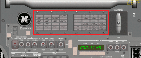
The Caution and Warning System lights indicate a failure or an unusual condition in one of the spacecraft systems.
Some lights will remain on until they are manually reset using the appropriate switch, others will turn off automatically when the condition no longer applies. Usually when any light comes on it will trigger the MASTER ALARM lights and sound.
The specific conditions which can light each of the lights are as followsAOH:
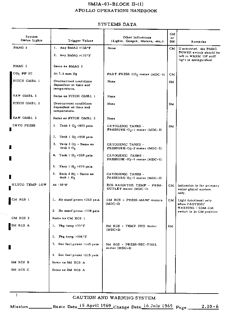
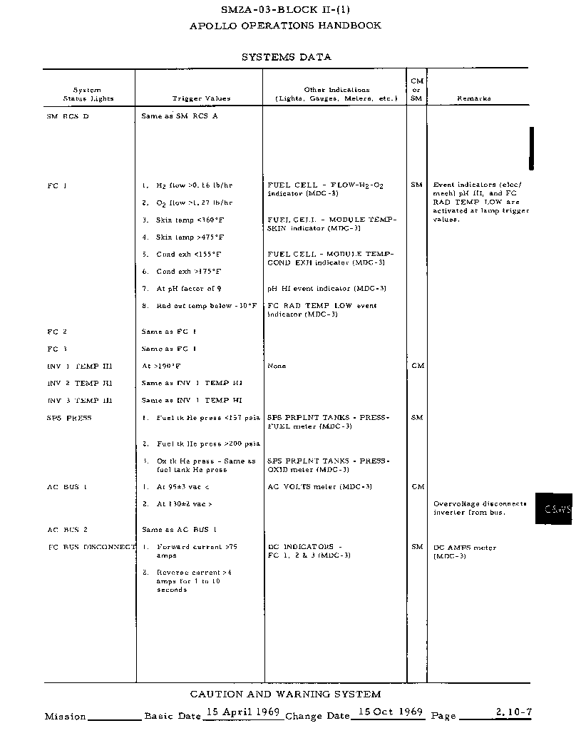
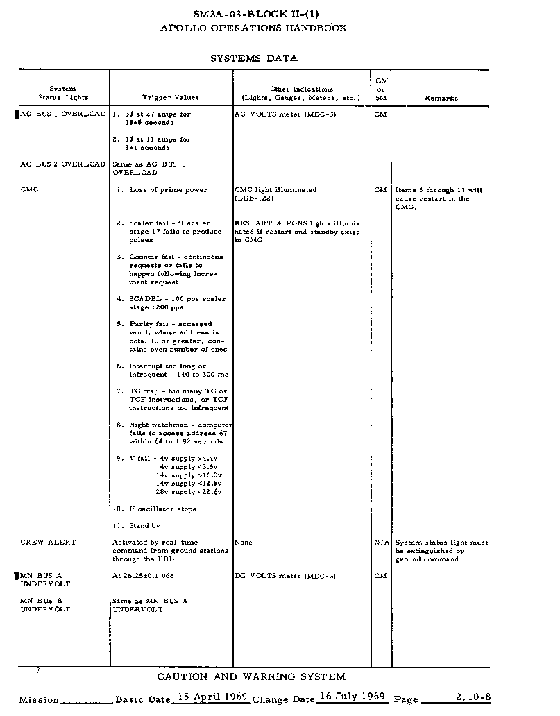
Note that Project Apollo may not simulate all warning conditions at this time, but eventually it will simulate them all.
Controls
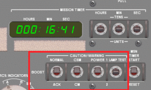
A number of switches on the control panel are used to control the Caution and Warning System.
CWS NORMAL/BOOST/ACK
In NORMAL mode all MASTER ALARM lights will light when an error occurs. In BOOST mode the left-hand MASTER ALARM light is disabled to avoid confusing the crew, as it is near the ABORT light on the panel.
CWS CM/CSM
Enable or disable monitoring of the Service Module Systems. In the CM position the CWS will only monitor the Command Module systems. You will be unable to test the lights for Service Module systems with this switch in the CM position.
The Caution and Warning System does not know when you seperate the Command Module from the Service Module. When this occurs, it will suddenly lose contact with the Service Module systems and many lights will go on. To avoid this, remember to set the CWS CM/CSM switch to CM before separating the Command Module.
CWS POWER 1/2
The Caution and Warning System has two internal power supplies. This switch allows you to select which power supply is currently in use, in case one system fails. You can also turn off the CWS by setting the switch to the center position.
CWS LAMP TEST 1/2
Position 1 tests the left-hand set of warning lights. Position 2 tests the right-hand set of warning lights. The center position (spring-loaded) disables light testing.
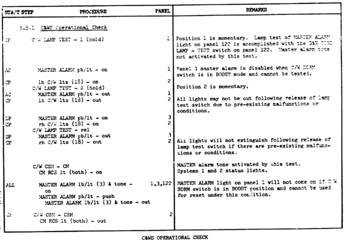
C&WS operational check
This procedure is used for regular checking the caution and warning system components in order to ensure, for example, that no lights have burnt out ASTP_AOH2.
<biblio force=false>
</biblio>
