Display and Keyboard Assembly: Difference between revisions
imported>Mark Grant (→Lights panel: - added all lights, not sure what some do.) |
imported>Mark Grant (Not really a stub anymore, I'll write they keyboard section later when I remember what they all do.) |
||
| Line 70: | Line 70: | ||
|PRIORITY DISPLAY|| | |PRIORITY DISPLAY|| | ||
|} | |} | ||
==Keyboard== | |||
The keyboard is used to enter data for the computer and respond to alerts from the computer. | |||
[[Category:CSM systems]] | [[Category:CSM systems]] | ||
[[Category:LM systems]] | [[Category:LM systems]] | ||
[[Category:Apollo Guidance Computer]] | [[Category:Apollo Guidance Computer]] | ||
Revision as of 13:17, 17 November 2006

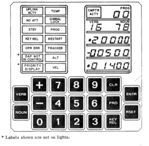
The Display and Keyboard Assembly (DSKY) was the main interface between the crew and the Apollo Guidance Computer which controlled the Command and Service Module.
Overview
The DSKY is split into three functional areas:
- The LED display, which is used to show information about the program which is running, data relevant to the program, and data that the astronaut is entering into the program.
- The lights panel, which indicates an unusual situation in the computer (e.g. a program error).
- The keyboard, which is used to enter new data to the program and confirm operations that are difficult or impossible to reverse (e.g. verifying an engine burn before ignition).
Programs, Verbs and Nouns
Interacting with the DSKY requires an understanding of the basic design of the AGC software. In particular, the concepts of Program (also referred to as Major Mode), Verb and Noun.
The Program determines the mode the computer is operating in. For example, Program 11 in the CM monitors the launch of the Saturn and displaying data on the DSKY in the LED display. Program 63 in the LM controls the braking phase of the automated lunar landing. So you need to know the program number to determine what the computer is trying to do.
The Verb specifies further optional actions that the computer can take, which may or may not be valid in all programs. For example, Verb 06 is used to display data from the computer on the LED display, while Verb 75 is used to start the launch monitoring program running if the computer didn't start it automatically at liftoff.
The Noun provides further information to the Verb. In the Verb 06 case, this specifies what data the computer should display; for example, Verb 06 and Noun 36 shows the current setting of the AGC's internal clock, whereas Verb 75 doesn't care what the Noun is set to.
For further information which Programs, Verbs and Nouns are supported, see pages specific to the version of the AGC you are using.
LED Display
The LED Display is divided into five lines.
The top line has the COMP ACTY light and the Program number display. The Program number is simple: it's the program the computer is currently running. The COMP ACTY light indicates the state of the computer; when it is actively performing calculations the light will be lit, whereas when it is idle the light will be out. In most cases you'll see the light flash on and off, but in particularly compute-intensive parts of the program it may stay on for several seconds.
The second line shows the current Verb and Noun numbers, or the values that the user is currently entering from the keyboard.
The bottom three lines are reserved for either output data from the computer or input data from the user. They are referred to as R1, R2 and R3 from top to bottom (for Register 1, 2, and 3). The first character on the line can be a + or - symbol or blank; + is a positive base-ten number, - is a negative base-ten number, while a number displayed with a blank is an octal (base-8) number.
Lights panel
The number of lights on the panel varies between the CM and LM DSKYs, so not all of these lights will be seen in the CM.
| Light | Function |
|---|---|
| UPLINK ACTY | Indicates that the AGC is receiving uplink telemetry from the ground. |
| TEMP | Indicates that the AGC is outside normal temperature limits. |
| NO ATT | Indicates that the AGC is not receiving valid attitude data from the Inertial Measurement Unit. |
| GIMBAL LOCK | Indicates that the IMU gimbals have locked. |
| STBY | Indicates that the AGC is in the low-power standby mode. |
| PROG | Indicates that a Program Alarm (aka internal error) has occured. The Alarm number can be viewed using the DSKY to determine the precise error. |
| KEY REL | The computer wants to display data in the R1 to R3 registers, but the user is currently entering data from the keyboard so those values cannot be updated. |
| RESTART | The computer is restarting, probably because of a hardware problem (e.g. a voltage spike). |
| OPR ERR | 'Operator Error' - the user made an error, typically entering invalid data. |
| TRACKER | |
| ALT | |
| VEL | |
| DAP NOT IN CONTROL | |
| PRIORITY DISPLAY |
Keyboard
The keyboard is used to enter data for the computer and respond to alerts from the computer.