Environmental Control System (CSM): Difference between revisions
imported>Mark Grant (Link and system diagram.) |
imported>Tschachim m (Printing improved) |
||
| Line 1: | Line 1: | ||
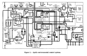
[[Image:CSMECSDiagram.png|thumb|right|CSM Environmental Control System]] | [[Image:CSMECSDiagram.png|thumb|right|CSM Environmental Control System]] | ||
This section provides step-by-step examples and instructions how to use the '''Environmental Control System (ECS)'''. Hopefully this will help users to get a better understanding and feeling how to | This section provides step-by-step examples and instructions how to use the '''Environmental Control System (ECS)'''. Hopefully this will help users to get a better understanding and feeling how to use the spacecraft systems. In the following procedures it is assumed that the spacecraft is in a "stable condition" without flying manoeuvers with ECS in "flight configuration", for example during Trans Lunar Coast and you can use time acceleration up to 1000 to assure that all of the internal systems have reasonable reaction times. | ||
== ECS monitoring check == | == ECS monitoring check == | ||
| Line 7: | Line 7: | ||
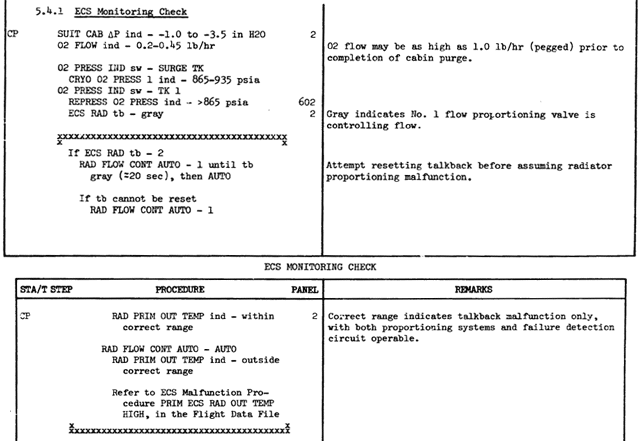
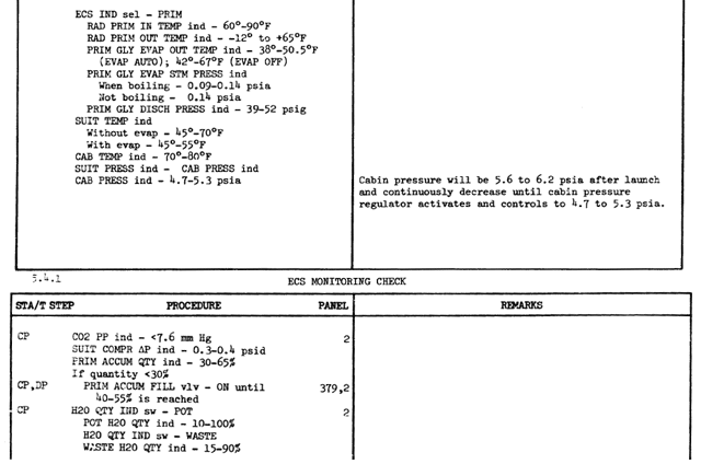
This is the part of the original Apollo documentation<cite>ASTP_AOH2</cite> used for regular checking the most important ECS components. | This is the part of the original Apollo documentation<cite>ASTP_AOH2</cite> used for regular checking the most important ECS components. | ||
[[Image: | [[Image:CSM_ECS_monitoring_check1.gif]] | ||
[[Image:CSM_ECS_monitoring_check2.gif]] | |||
== Suit compressor shutdown and restart == | == Suit compressor shutdown and restart == | ||
| Line 13: | Line 15: | ||
During normal operations suit compressor 1 is turned on in order to drive the suit atmosphere regeneration systems, which remove CO<sub>2</sub>, water and other unwanted substances. Suit compressor 2 is redundant and turned off. The following procedure demonstrates the necessity of the suit compressor. | During normal operations suit compressor 1 is turned on in order to drive the suit atmosphere regeneration systems, which remove CO<sub>2</sub>, water and other unwanted substances. Suit compressor 2 is redundant and turned off. The following procedure demonstrates the necessity of the suit compressor. | ||
* | * Normally the SUIT COMPRESSOR 1 switch is in AC1 position (that means on) and the SUIT COMPRESSOR 2 switch is in OFF position. The SUIT COMPR ΔP meter shows 0.3 - 0.4 psi, the PART PRESS CO<sub>2</sub> meter shows appox. 2 mmHg, which is far below the CO<sub>2</sub> PP HI value of 7.6 mmHg, so the suit compressor is working properly. | ||
* Switch the SUIT COMPRESSOR 1 switch to OFF (center position). The SUIT COMPR ΔP meter drops to 0 psi within a few seconds indicating that the compressors stopped working. You get a SUIT COMPRESSOR alarm, push the MASTER ALARM pushbutton/light to turn off the alarm. The PART PRESS CO<sub>2</sub> meter begins to increase. | * Switch the SUIT COMPRESSOR 1 switch to OFF (center position). The SUIT COMPR ΔP meter drops to 0 psi within a few seconds indicating that the compressors stopped working. You get a SUIT COMPRESSOR alarm, push the MASTER ALARM pushbutton/light to turn off the alarm. The PART PRESS CO<sub>2</sub> meter begins to increase. | ||
Revision as of 22:51, 18 December 2006

This section provides step-by-step examples and instructions how to use the Environmental Control System (ECS). Hopefully this will help users to get a better understanding and feeling how to use the spacecraft systems. In the following procedures it is assumed that the spacecraft is in a "stable condition" without flying manoeuvers with ECS in "flight configuration", for example during Trans Lunar Coast and you can use time acceleration up to 1000 to assure that all of the internal systems have reasonable reaction times.
ECS monitoring check
This is the part of the original Apollo documentationASTP_AOH2 used for regular checking the most important ECS components.
Suit compressor shutdown and restart
During normal operations suit compressor 1 is turned on in order to drive the suit atmosphere regeneration systems, which remove CO2, water and other unwanted substances. Suit compressor 2 is redundant and turned off. The following procedure demonstrates the necessity of the suit compressor.
- Normally the SUIT COMPRESSOR 1 switch is in AC1 position (that means on) and the SUIT COMPRESSOR 2 switch is in OFF position. The SUIT COMPR ΔP meter shows 0.3 - 0.4 psi, the PART PRESS CO2 meter shows appox. 2 mmHg, which is far below the CO2 PP HI value of 7.6 mmHg, so the suit compressor is working properly.
- Switch the SUIT COMPRESSOR 1 switch to OFF (center position). The SUIT COMPR ΔP meter drops to 0 psi within a few seconds indicating that the compressors stopped working. You get a SUIT COMPRESSOR alarm, push the MASTER ALARM pushbutton/light to turn off the alarm. The PART PRESS CO2 meter begins to increase.
- After about 10 minutes the PART PRESS CO2 meter shows a pressure of 7.6 mmHg or higher, the suit atmosphere gets seriously poisoned. You get a CO2 PP HI alarm, push the MASTER ALARM pushbutton/light to turn off the alarm. The O2 FLOW meter shows a decreased flow because the suit circuit is no longer supplied with fresh oxygen.
- Switch the SUIT COMPRESSOR 1 switch back to AC1. The SUIT COMPR ΔP meter goes back to 0.3 - 0.4 psi, the SUIT COMPRESSOR alarm goes away, the PART PRESS CO2 meter slowly begins to decrease.
- After a few minutes the CO2 PP HI alarm goes away. After about 1 hour the PART PRESS CO2 meter should show approx. 2 mmHg and is normal again.
Cooling with the primary water-glycol coolant loop
| ||
| Because of the work-in-progress of the ECS this procedure is not working at the moment. |
At the moment the primary and secondary water-glycol cooling systems are only used to control the suit and cabin temperature. The suit is heated by the crew at about 10 W per crew member. In reality the cooling system also has to cool all the electrical devices like the IMU or the BMAGs and so has to remove much more heat from the CSM. But the heating of these devices is not simulated at the moment, so the cooling systems are running quite idle in the initial state, all temperatures are very low.
To test and play with the primary water-glycol coolant loop you can use the HIGH GAIN ANTENNA PITCH POSITION switch to heat the coolant loop with a boiler. Of course this is not the realistic functionality of this of switch, but that way you can watch the behavior of the cooling system during different heat loads. If the HIGH GAIN ANTENNA PITCH POSITION switch is set to +90° (up) there's no additional heating, each position adds 800 W of heating power, so in the -90° position (down) the coolant loop is heated with a heating power of 4800 W, which is about the maximum heat the primary loop can deal with.
With the following procedure you can discover the behavior of the primary water-glycol coolant loop during various heat loads:
- Set the HIGH GAIN ANTENNA PITCH POSITION switch to +90° to disable the heating, set the ECS INDICATORS switch to PRIM to make sure you're monitoring the primary loop and use time acceleration between 10 to 100 and wait until the ECS meters are in a stable condition.
- The ECS RAD TEMP INLET meter indicates a temperature lower than 60 °F, the ECS RAD TEMP PRIM OUTLET meter shows about -10 °F maintained by the primary ECS radiators heater. The GLY EVAP TEMP OUTLET meter shows ca. 45 °F, the GLY EVAP STEAM PRESS meter is a little bit under 0.15 psi indicating that the evaporator steam pressure control valve is closed. Because the primary coolant loop has only to remove the small heat load caused by the crew the evaporator is not evaporating and the radiators have only a small amount of thermal energy to radiate, the outlet has to be heated to maintain the minimum temperature. If you switch the ECS RADIATORS HEATER PRIM switch to OFF (center) you can see the outlet temperature drop down. You get a GLYCOL TEMP LOW alarm, push the MASTER ALARM pushbutton/light to turn off the alarm. Switch the ECS RADIATORS HEATER PRIM switch to PRIM 1 (up) again, the GLYCOL TEMP LOW alarm goes away.
- Set the HIGH GAIN ANTENNA PITCH POSITION switch to 0° to enable medium heating and wait a few minutes until the ECS meters are in a stable condition again.
- The ECS RAD TEMP INLET meter indicates now a temperature of about 70 °F to 80 °F, the ECS RAD TEMP PRIM OUTLET meter shows about 20 °F to 40 °F. The GLY EVAP TEMP OUTLET meter shows still about 45 °F, the GLY EVAP STEAM PRESS meter is still a little bit under 0.15 psi indicating that the evaporator is still not necessary. All the thermal energy is now removed and radiated to the space by the ECS radiators, as indicated by the higher radiator outlet temperature.
- Set the HIGH GAIN ANTENNA PITCH POSITION switch to -60° to enable a huge amount of heat and wait a few minutes until the ECS meters are in a stable condition again.
- The ECS RAD TEMP INLET meter indicates now a temperature of about 90 °F, the ECS RAD TEMP PRIM OUTLET meter shows about 50 °F. Now the radiators are no longer capable removing all the thermal energy from the water-glycol coolant and the evaporator mode of cooling is initiated. The GLY EVAP TEMP OUTLET meter shows about 40 °F, the GLY EVAP STEAM PRESS meter is about 0.12 psi. That means that the steam pressure control valve is now partially open and the evaporator removes the remaining thermal energy by evaporating waste water to the space.
- Set the HIGH GAIN ANTENNA PITCH POSITION switch to -90° to enable maximum heating. Wait a few minutes and you will notice that the GLY EVAP STEAM PRESS meter is further decreasing. Wait and see if the evaporator (together with the still operating radiators) can remove all this heat from the coolant...
- Set the HIGH GAIN ANTENNA PITCH POSITION switch back to 0° to enable medium heating again. The temperatures will go back to normal readings.
Primary water-glycol coolant loop manual control
| ||
| Because of the work-in-progress of the ECS this procedure is not working at the moment. |
In the previous procedure we changed the amount of heat the primary water-glycol coolant loop had to remove, the radiators and the evaporator were controlled automatically by the ECS with respect to the amount of thermal energy they had to remove from the coolant. But you also can control both systems manually in case the automatic control fails (but this is not possible at the moment) or you want a different behavior of these systems:
- Set the HIGH GAIN ANTENNA PITCH POSITION switch to 0° to enable medium heating and wait a few minutes until the ECS is in a stable condition again.
- The radiators are sufficient to remove all the heat, the ECS RAD TEMP INLET meter indicates a temperature of about 70 °F to 80 °F, the ECS RAD TEMP PRIM OUTLET meter shows about 20 °F to 40 °F. The evaporator is not necessary, the GLY EVAP TEMP OUTLET meter shows about 45 °F, the GLY EVAP STEAM PRESS meter is again a little bit under 0.15 psi indicating that the steam pressure control valve is closed.
- Now we disable the radiators: Switch the ECS RADIATORS FLOW CONT PWR switch to MAN SEL MODE (down) and the ECS RADIATORS MAN SEL switch to OFF (center). The radiators are bypassed, the ECS RAD TEMP PRIM OUTLET meter increases to about 80 °F within a few minutes. Now the evaporator has to remove all the heat, the GLY EVAP STEAM PRESS meter indicates about 0.09 psi, GLY EVAP TEMP OUTLET meter shows about 50 °F. That means the evaporator is running at full evaporation and is hardly capable of cooling the water-glycol.
- Switch the ECS RADIATORS FLOW CONT PWR switch back to PWR and wait a few minutes until the ECS is back in the previous state.
- Now we try manual operation of the evaporator: Switch the GLYCOL EVAP STEAM PRESS AUTO MAN switch to MAN. Now you can control the steam pressure control valve manually with the GLYCOL EVAP STEAM PRESS INCR DECR switch. Switch and hold it to DECR to open the valve. The GLY EVAP TEMP OUTLET meter quickly drops below 40 °F indicating that there's more cooling than necessary. You can play with different steam pressures and monitor the GLY EVAP TEMP OUTLET meter to see the effect.
- Switch the GLYCOL EVAP STEAM PRESS AUTO MAN switch to AUTO, all ECS systems are back to automatic control.
<biblio force=false>
</biblio>

