Command Module Reaction Control System: Difference between revisions
imported>Abr35 mNo edit summary |
imported>Abr35 No edit summary |
||
| Line 17: | Line 17: | ||
When fired, the injector valves allow fuel and oxidizer to impinge on a splash plate in the combustion chamber. The reaction is expelled through the engine nozzle which is mounted inside the Command Module. | When fired, the injector valves allow fuel and oxidizer to impinge on a splash plate in the combustion chamber. The reaction is expelled through the engine nozzle which is mounted inside the Command Module. | ||
After Service Module separation, control of the spacecraft is automatically handed over to the CM RCS. However, if this fail to happen, the TRNFR CM/SM switch can manually switch RCS control over to the Command Module. The switch is spring loaded and will re-center after RCS command is changed. If the switch is accidently moved, switch it down will change control back to the SM RCS. | After Service Module separation, control of the spacecraft is automatically handed over to the CM RCS. However, if this fail to happen, the TRNFR CM/SM {{panel label|name=2.C}} switch can manually switch RCS control over to the Command Module. The switch is spring loaded and will re-center after RCS command is changed. If the switch is accidently moved, switch it down will change control back to the SM RCS. | ||
=Logic= | =Logic= | ||
During the entry phase of the mission, the CM RCS Logic provides control over sequencing of different events during the Command Modules approach, entry, and descent. On Command Service Module separation, the CM RCS Logic automatically fires the squibs in the CM RCS helium tanks, pressurizing the whole system. This applies also during an abort, allowing the CM RCS to be activated more quickly. As the Command Module descends into the thicker atmosphere, the logic disables the RJ/EC commands to the CM RCS's automatic coils. This prevents the CM from firing its RCS without input from the astronaut. Finally, the CM RCS Logic provides control over helium and fuel purges during the descent. The CM RCS contains chemicals which could be harmful to the divers and recovery teams. The helium is purged by allowing it to bypass the propellant tanks and flow directly out of the Command Module. This is done at a predetermined altitude if the CM PRPLNT PURGE switch {{panel label|name=1.C}} is up. Alternatively, the CM RCS He DUMP push button can be depressed to perform this manually. The CM RCS propellants will also be depleted by the direct coils at a preset altitude when the CM PRPLNT DUMP switch {{panel label|name=1.B}} is set to up. This can be performed manually by the astronaut using RHC direct. | |||
{{stub}} | {{stub}} | ||
Revision as of 16:19, 2 April 2011
CM RCS Overview
The Command Module RCS is nearly identical in function to the Service Module RCS with a few exceptions. Firstly, The SM RCS contains 16 rockets in 4 separate sub-systems. This set up allows for the Command Service Module stack to be controlled in 6 ranges of motion. The CM RCS contains only 12 rockets in two completely redundant sub-systems named system 1 and system 2. These 12 reaction control jets allow the command module to be rotated in pitch, roll, and yaw, but they do not allow for any translational movement. The SM RCS is designed for versatility. The CM RCS has the sole purpose of controlling the Command Module's orientation during Entry and Launch Aborts. Being this is such a crucial moment of the flight, the Command Module's RCS was designed with utility and redundancy in mind.
Heaters

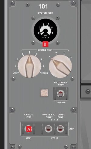
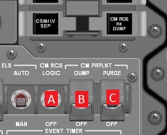
With the exception of launch aborts, the Command Module RCS must first be heated in order to be properly used. Under normal conditions, the CM RCS is heated just prior to Entry and will only function afterward. The CM RCS heaters can be supplied with current from the main buses by using the CM HEATER circuit breakers on MDC-8. The CM RCS logic switch on MDC-1 1.A must also be on for heaters to function. The CM RCS HTRS switch on LEB-101 101.A activates the CM RCS heaters. They must be heated for a period of roughly 20 minutes before use. The heaters also provide data on temperature to the SYSTEMS TEST panel on LEB-101 101.B. This is not yet implemented in the current version of NASSP.
Helium

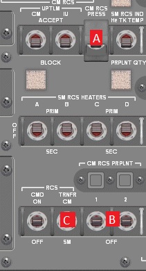
Before pressurizing the CM RCS, the CM RCS HTRS must first be set to off. The CM RCS propellant tanks are pressurized with helium. The valves for the helium tanks are squib operated, and an explosive charge fires to open the helium isolation valves. The CM RCS PRESS switch located on MDC-2 pressurizes the propellant tanks. 2.A The switch is guarded and must be opened before being used. Alternatively, aborts, and service module separation will pressurize the tanks. Command Module RCS subsystems 1 and 2 are both pressurized at higher pressure than the Service Module Quads, but otherwise the regulators, check valves and burst valves are nearly identical to their SM RCS counterparts. When the CM RCS systems are pressurized pressure from the helium bladders force oxidizer and fuel out of the tank into a diffuser tube and out into the manifolds.
Propellant
The CM RCS propellant isolation valves are opened by using the CM RCS 1 and 2 switches on MDC-2. 2.B CM RCS 1 opens system 1 and CM RCS 2 opens system 2. These isolation valves are magnetically sealed solenoids that must be opened elctronically, but can magnetically close when the CM RCS PRPLNT switch is in the down position. They are identical to the SM RCS propellant isolation valves. A grey talkback means the valves are open, while a barber pole (white and black diagonal lines) talkback indicates that the valves is shut.
Engine

The engine injector valves consist of two coils, an automatic and manual coil, same as in the SM RCS. The automatic coil is opened and closed by the RJ/EC and the direct coil takes commands from RHC direct. This is further explained in the SCS section.
When fired, the injector valves allow fuel and oxidizer to impinge on a splash plate in the combustion chamber. The reaction is expelled through the engine nozzle which is mounted inside the Command Module.
After Service Module separation, control of the spacecraft is automatically handed over to the CM RCS. However, if this fail to happen, the TRNFR CM/SM 2.C switch can manually switch RCS control over to the Command Module. The switch is spring loaded and will re-center after RCS command is changed. If the switch is accidently moved, switch it down will change control back to the SM RCS.
Logic
During the entry phase of the mission, the CM RCS Logic provides control over sequencing of different events during the Command Modules approach, entry, and descent. On Command Service Module separation, the CM RCS Logic automatically fires the squibs in the CM RCS helium tanks, pressurizing the whole system. This applies also during an abort, allowing the CM RCS to be activated more quickly. As the Command Module descends into the thicker atmosphere, the logic disables the RJ/EC commands to the CM RCS's automatic coils. This prevents the CM from firing its RCS without input from the astronaut. Finally, the CM RCS Logic provides control over helium and fuel purges during the descent. The CM RCS contains chemicals which could be harmful to the divers and recovery teams. The helium is purged by allowing it to bypass the propellant tanks and flow directly out of the Command Module. This is done at a predetermined altitude if the CM PRPLNT PURGE switch 1.C is up. Alternatively, the CM RCS He DUMP push button can be depressed to perform this manually. The CM RCS propellants will also be depleted by the direct coils at a preset altitude when the CM PRPLNT DUMP switch 1.B is set to up. This can be performed manually by the astronaut using RHC direct.