Service Module Reaction Control System

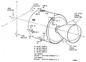
The Service Module Reaction Control System (SM RCS) is utilized to control spacecraft rates and rotation in all three axis in addition to any minor translation maneuvers including SPS ullage thrust and separation maneuvers. It consists of four individual, functionally identical packages, located 90° apart around the forward (+X axis) of the SM periphery. Each package, called a "quad", has four reaction engines mounted on the outer surface. The engines use monomethylhydrazine (MMH) as fuel and inhibited nitrogen tetroxide oxidizer, each engine has about 100 lbf (441.5 N) thrust. This hypergolic fuel combination is pressurized with helium during thrusting periods, so no propellant pump is needed. The propellant flow from the tanks to the thrust chambers is controlled by electric engine injector solenoid valves.
SM RCS Overview
The Service Module RCS contains 16 reaction control jets grouped into clusters of four, or quads. These four quads are placed 90 degrees apart about the circumference of the service module. The quads are designated A-D clockwise with Quad A being on the top of the service module. Each quad's thrusters are numbered 1 through 4. Thrusters 1 and 2 control roll and 3 and 4 control either pitch or yaw, depending on the quad.
The engine nozzles on each quad are canted approximately 10 degrees away from the Service Module's skin to prevent damage when the rockets fire. The roll engines are offset from one another to accommodate the quad's plumbing. Each RCS quad has its own individual fuel and plumbing systems. Each quad operates as its own independent system. For example, if quad A's fuel is depleted or if the quad's plumbing is damaged, this will not prevent any other quad from being used. The functions and structures of each quad are identical.
Helium

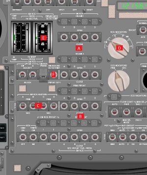
Helium is used to pressurize the fuel and oxidizer tanks and allow the gasses to be expelled in zero-gravity. Each quad has two independent Helium tanks with a magnetically latched helium isolation valve. In order to allow helium pressurization of the RCS propellants, the isolation valve solenoid must first be unlatched. Eight spring loaded switches on MDC-2, labeled HELIUM 1 and HELIUM 2 2.A control helium isolation solenoids for tanks 1 and 2 in each quads. If the square talkback indicator for a particular solenoid is barber-pole (meaning it displays white and black diagonals) the helium tank is blocked from the rest of the quad. Switching one of the helium switches into the up position will energize the solenoid and open the helium tank. When it's talk back is gray the helium tank is open and helium is flowing out of the tank. Switching the helium switch down will unlatch the solenoid and it will magnetically close without the need for electrical impulse.
The helium passes through a forward flowing check valve. This valve prevents any RCS propellants from flowing backwards into the helium tanks. After the check valve, the helium flows through two helium regulators operating in parallel. These regulators control the flow of helium into a bladder which surrounds the RCS propellant tanks. Should one of the regulators fail, the other will increase flow to ensure proper helium pressure. Finally, the helium bladders contain a burst valve, which will relieve pressure in the helium bladders, should it rise too high.
Propellant

The propellant tanks are surrounded by a helium bladder which, when filled, pressurizes the propellant tanks. Once the tanks are pressurized, they must also be opened in order for the fuel and ocidizer to mix. Each RCS quad has both a primary and a secondary propellant tank. These have individual isolation valves in between them and the engine. The controls for these valves are located below the helium isolation valves on MDC-2 2.B and work in exactly the same manner. These are labeled PRIM PRPLNT for the primary isolation valves and SEC PRPLNT for the secondary valves. The propellant isolation valves receive current from the either or both of the main buses by closing the circuit breakers on MDC-8 labeled SM RCS - PRPLNT ISOL 8.A.
Once the fuel isolation valves have been opened fuel can flow ahead into the quad's injector valves. Just like most rocket engines, the SM RCS consists of both Fuel (MMH) and Oxidizer (NO4) which are pumped into a combustion chamber by the injection valves, and then expelled out of the engine nozzle. The force from the resulting reaction provides attitude control. A fuel injector valve consists of two separate coils, an automatic and direct coil. The automatic coils receive commands to fire from the RJ/EC and the direct coil is commanded by the RHC. For more information on this consult the Stabilization and Control System section. The injectors are all magnetically shut and must receive commands from either the RJ/EC or the RHC to open and fire. In order for the automatic coils to function the SM RCS logic circuit breakers 8.C on MDC-8 must be closed.
Engine
When an RCS engine fires, the fuel and oxidizer cross in the premix chamber first before entering the combustion chamber. This is done to ensure a steady output of force when the engine is fired and minimize transients. Being a burst from a rocket engine is a chemical reaction, the reaction builds and generates more force when the reactants mix. As the reactants are depleted, the force exerted by the rocket also tails-off. This brief build-up and tail-off of force from the RCS rockets are referred to as their start and shut-off transients. These transients are not yet implemented in the current version of NASSP.
Each quad is heated by two SM RCS Heaters that activate and deactivate based on temperature sensors. These heaters can be given current via their SM RCS - SM RCS HEATERS circuit breakers on MDC-8 8.B. Normally only one of the two heaters operate at a time in each quad, and they can be configured by the SM RCS HEATER switches on MDC-2. The SM RCS indicator gauges on MDC-2 2.E also allow the astronaut to monitor package temperatures for any of the quads. From left to right this gauge displays: package temperature, helium pressure, secondary fuel pressure, and either helium temperature or fuel quantity. This fourth indicator displays one of two values, which can be selected by the SM RCS IND switch 2.F. The rotary switch on MDC-2 2.D will select which package's temperature is represented on the gauge. Should temperatures in any of the quads fall too low, it's appropriate caution and warning light will illuminated and the master alarm will sound. This happens regardless of which package is currently displayed.
If the SM RCS IND switch 2.F is switched to quantity, a temperature-pressure transducer can monitor the propellant tanks and estimate the quantity of fuel remaining in each package. Remember that each quad's propellant is independent. Also remember that primary and secondary propellant tanks are independent in each quad, so if the primary tank is depleted, you must manually open the secondary isolation valve. Should the RCS quantity fall too low, the caution and warning system will alert you, just as it would for temperatures. When the switch is set to up the temperatures in the helium tank are displayed on the gauge.