Reaction Control System (CSM): Difference between revisions
imported>Tschachim (Work in progress...) |
imported>Tschachim (Done for now.) |
||
| Line 6: | Line 6: | ||
{{mainarticle|Service Module Reaction Control System}} | {{mainarticle|Service Module Reaction Control System}} | ||
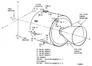
The Service Module Reaction Control System (SM RCS) consists of four individual, functionally identical packages, located 90° apart around the forward (+X axis) of the SM periphery. Each package, called a "quad", is such that the reaction engines are mounted on the outer surface of the panel and the remaining components are inside. | |||
Each RCS package incorporates a pressure-fed, positive-expulsion, pulse-modulated, bipropellant system to produce the reaction thrust required to perform the various SM RCS control functions. | |||
<br clear="right"> | <br clear="right"> | ||
== Command Module Reaction Control System == | == Command Module Reaction Control System == | ||
| Line 15: | Line 18: | ||
{{mainarticle|Command Module Reaction Control System}} | {{mainarticle|Command Module Reaction Control System}} | ||
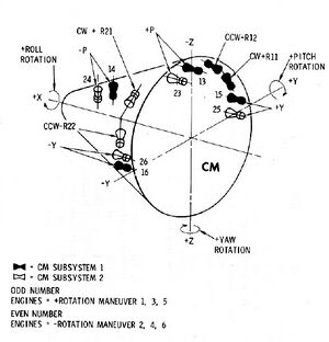
The Command Module Reaction Control System (CM RCS) provides the impulse required for controlling spacecraft rates and attitude during the terminal phase of the mission after SM separation. | |||
The CM RCS consists of two similar and independent subsystems, identified as system 1 and system 2. The CM RCS is contained entirely within the CM and each reaction engine nozzle is ported through the CM skin. The CM RCS uses the same propellants and pressurization as the SM RCS. | |||
<br clear="right"> | <br clear="right"> | ||
<biblio force=false> | <biblio force=false> | ||
#[[References]] | #[[References]] | ||
</biblio> | </biblio> | ||
[[Category:Reaction Control System (CSM)| ]] | [[Category:Reaction Control System (CSM)| ]] | ||
Revision as of 20:22, 7 June 2008
The Reaction Control System (RCS) provides the thrust to control spacecraft rates and rotation in all three axis in addition to any minor translation maneuvers. The CSM includes two separate reaction control systems designated Service Module Reaction Control System and Command Module Reaction Control System. Both systems are controlled either manually or automatically by the CMC or the SCS.
Service Module Reaction Control System

 |{{#if:|, | and }}[[{{{2}}}|{{{2}}}]]}}{{#if:
 |{{#if:|, |, and }}[[{{{3}}}|{{{3}}}]]}}{{#if:
 |{{#if:|, |, and }}[[{{{4}}}|{{{4}}}]]}}{{#if:
|, and [[{{{5}}}|{{{5}}}]]}}{{#if: | (too many parameters in {{mainarticle}})}}
The Service Module Reaction Control System (SM RCS) consists of four individual, functionally identical packages, located 90° apart around the forward (+X axis) of the SM periphery. Each package, called a "quad", is such that the reaction engines are mounted on the outer surface of the panel and the remaining components are inside.
Each RCS package incorporates a pressure-fed, positive-expulsion, pulse-modulated, bipropellant system to produce the reaction thrust required to perform the various SM RCS control functions.
Command Module Reaction Control System

 |{{#if:|, | and }}[[{{{2}}}|{{{2}}}]]}}{{#if:
 |{{#if:|, |, and }}[[{{{3}}}|{{{3}}}]]}}{{#if:
 |{{#if:|, |, and }}[[{{{4}}}|{{{4}}}]]}}{{#if:
|, and [[{{{5}}}|{{{5}}}]]}}{{#if: | (too many parameters in {{mainarticle}})}}
The Command Module Reaction Control System (CM RCS) provides the impulse required for controlling spacecraft rates and attitude during the terminal phase of the mission after SM separation.
The CM RCS consists of two similar and independent subsystems, identified as system 1 and system 2. The CM RCS is contained entirely within the CM and each reaction engine nozzle is ported through the CM skin. The CM RCS uses the same propellants and pressurization as the SM RCS.
<biblio force=false>
#References
</biblio>