Electrical Power System (CSM)
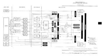
The Electrical Power System (EPS) supplies electrical power to almost all CSM systems.
Power generation and storage
Main power sources are:
- 3 fuel cells (FC 1,2,3)
- 3 29V/40Ah silver oxide-zinc batteries (BAT A, B, C)
- 2 23V/0,75Ah silver oxide-zinc batteries for pyrotechnics (PYRO BAT A, B)
Fuel cells
The fuel cells form the main source of electrical power. By reacting Oxygen (02) und Hydrogen (H2), electricity, heat and water (H2O) are produced. Electricity is distributed to the CSM systems, the excess heat is radiated to space, water is distributed to the Environmental Control System (ECS). The FC power plants are completely independent from each other, they only share the cryogenic manifold and the O2/H2 vents.
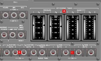
O2 and H2 are stored in cryogenic form in tanks (2 each). Each O2 tank stores 320lbs of cryogenic oxygen at 900+/-35 psia, each H2 tank 28 lbs H2 at 245+15/-20 psia. Quantity and pressure in each tank can be monitored at MDC-2 2.A. When the pressure in a O2 tank falls below 800 psia or exceeds 950 psia, the CRYO PRESS warning light will come on with a master alarm (H2 limits: 220 to 270 psia).
To maintain nominal pressure in the tanks, each tank contains a heater to warm the cryogenic (thus raising pressure) and a fan to circulate the cryogenic to avoid stratification. The heaters and fans are controlled by the O2/H2 HEATERS 1 and 2 2.B(O2/H2 FANS 1 and 2 2.C, respectively) on MDC-2. In AUTO, the fans and heaters are controlled automatically by pressure switches, cycling to on when BOTH tank pressures fall below 225 psia and to off when one tank reaches 260 psia again (O2:on at 865psia, off at 935 psia). In OFF, power is disconnected from the fan/heater. The ON position provides direct power to the heater/fan. As no overpressure shut-off is provided, tank pressures have to be monitored carefully when HEATER switches are in ON. Also, when setting a HEATER-switch to ON, the FAN switch for this tank has also be set to ON, otherwise damage to the heater and/or uneven heating of the cryogenic may occur.
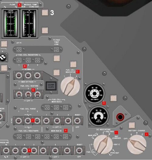
The H2/O2 tanks fed the FCs in conjunction over check valves; there are no provisions for isolating a tank from the manifold. The cryogenic flow to the FCs is controlled by shut-off valves, which are controlled by the FUEL CELL REACTANTS switches 3.H. By placing the switch to UP, the O2 and H2 shut-off valves of the respective FC are opened, when placed in DOWN closed. The switches are spring loaded to the CENTER position, which supplies no power to the valves and keeps them in the last commanded position. In a nominal flight the shut-off valves are open during pre-lunch and remain open throughout the flight. As the FCs are not restartable, closing the shut-off valves will result in a loss of the respective FC. To avoid inadverted loss of FCs, the FC REACS cbs on panel 226 remain open during flight, which cuts off electrical power to the FUEL CELL REACTANTS switches. As the shut-off valves are prone to fall close when exposed to vibrations, they can be latched in their positions by placing the FC REACS VALVES-switch 3.N to LATCH. This is normally done during dV-maneuvers (boost, SPS-thrusting) and separations. The position of the shut-off valves is indicated by talkbacks, which are situated above the respective switch (barberpole: closed, gray: open).
After passing the shut-off valves, the reactants pass a preheater and reach a regulator, which provides the FCs with the nominal cryo-pressure. In the FC, O2 and H2 react to H2O-steam and generate electricity. The H20-steam is flushed out of the FC by the excessive H2 and flows in a condenser, carrying the waste heat with it. In the condenser, the H2O-steam/H2 mix is cooled by water/glycol. The H2O condenses and flows to a separator, which removes the excessive H2 and provides it to the FC again. After that, the H2O is fed to the ECS. The warm water/glycol is pumped through the O2 and H2 preheaters, enters the FC radiators, rejects its heat to space and enters the condenser again. A pump, one for each FC, circulates the water/glycol. Power to the pumps is controlled by the FUEL CELL PUMPS-switches 5.A. As the FCs only work when a minimum temperature of 360°F is maintained, the H2 entering the FC has to be preheated by heaters. These are controlled by the FUEL CELL HEATERS-switches 3.D. In ON the heaters maintain the correct H2-temp automatically. In OFF, they are disconnected from electrical power. Normal position is ON. When the FC has to carry minimal or no load, the temperature of the H2O/H2 exhaust can be so low that the water/glycol can not be heated to its proper temperature, thus providing insufficient preheat of the reactants entering the FC. This condition is indicated by the FC RAD TEMP LOW tb showing barberpole. To avoid this, 3/8 of the radiators can be bypassed, so that less heat is rejected and the water/glycol maintains its nominal temperature. The bypass is controlled by the FUEL CELL RADIATORS-switches 3.B. In NORMAL, the bypass-valve is closed, in EMER BYPASS open. Center position cuts off power to the valve. Talkbacks above the switches provide indicate position of the respective bypass-valve (gray: closed, barberpole: open). Normal position is gray (bypass closed).
Due to impurities in the reactants, the FCs need to be purged regularly. This is done by the FUEL CELL PURGE-switches 3.F. In the H2 PURGE-position, the H2-purge-valve of the respective FC is opened, which provides a high flow of H2 through the FC, which flushes out the impurities. As the contaminated exhaust of the FC cannot be fed back to it, it is vented overboard. The O2 PURGE-position opens the O2-purge-valve. In the center position, both purge-valves are closed. The H2 PURGE LINE HTR-switch 3.O has to be set to ON at least 20 min prior to an H2-purge to avoid freezing exhaust-H2O in the vent line.
Performance of the FCs can be monitored via the FC-instruments 3.A, which provide indication of O2-flow, H2- flow, skin-temp and cond(ensator outlet)-temp of the FC selected with the FUEL CELL INDICATOR-switch 3.C. Normal readings should be in the green area. The pH HI-talkback will change to barberpole when the pH factor of the exhaust H2O of the selected FC is over 9, which indicates that the electrolyte (potassium hydroxide) of this FC is leaking out. The damaged FC has to be shut down immediately. Critical parameters of the FCs are also monitored by the C&W system. The FC 1 (2,3) light will light and a master alarm will occur when the respective FC exceeds critical parametersI.
Batteries
3 silver oxide-zinc batteries form the source of power from SM-separation till splashdown. Additionally, they support the FCs in case of high power demands (dV-maneuvers). In normal flight, only BATs A and B are used for this, BAT C will be connected to the busses prior to SM-separation. All three BATs can be recharged by the BAT CHARGER.
Pyro batteries
2 silver oxide-zinc batteries supply power to the SECS pyrotechnics. They are not rechargeable and cannot be connected to the other systems.
Power distribution
DC
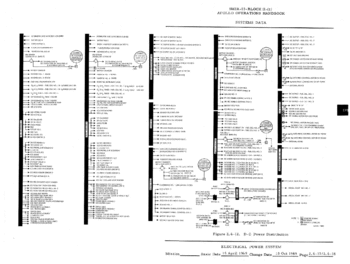
There are several DC-busses in the CSM:
- MAIN BUS A and B (provide power to nearly all CSM systems, powered by the SM BUSSES and/or BAT BUSSES)
- SM BUS A and B (provide power to major loads in the SM, e.g. SPS gimbal motors, powered by the FCs)
- BAT BUS A and B (powered by BATs)
- BAT RELAY BUS (powered by both BAT BUSSES)
- FLIGHT BUS (provides power to part of the TELCOMs, powered by both MAIN BUSSES)
- FLIGHT/POSTLANDING BUS (provides power to equipment which is vital after postlanding)
- NONESS BUS 1 and 2 (provide power to nonessential equipment)
Each SM BUS is tied directly to its corresponding MAIN BUS. The FCs can be connected to one or both SM BUSSES (and so to one or both MAIN BUSSES). This is done by the FUEL CELL MAIN BUS-switches 3.G. By putting one of these switches to ON, the respective FC is connected to the selected MAIN BUS by motor-switches. The center position arms the C&W "FC-BUS DISCONNECT" light for this FC. In OFF, the respective FC is disconnected from the MAIN BUS and the C&W-circuit is disarmed. Talkback indicators provide information of the status of the motor-switches (grey: FC connected to bus, barberpole: FC disconnected).
The most right RESET-switch in each row controls the undervoltage sensing circuit for the respective MAIN BUS. In the center position, the sensing circuit is armed and when the voltage of the respective bus drops below 26,15 Volts, the MAIN BUS A (B) UNDERVOLT warning light will come on, accompanied with a MASTER ALARM. The RESET-position resets the sensing circuit and extinguishes the warning light. In OFF, the sensing circuit is disarmed.
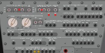
In addition to the FCs, MAIN BUS A can be powered by BAT BUS A and MAIN BUS B by BAT BUS B. Each BAT BUS is powered by its BAT via the BAT A (B) PWR ENTRY/POSTLANDING cb on panel 250. BAT C can be tied to either BAT BUS and to either MAIN BUS. Normally, the FCs provide power for the SC alone. When its is necessary to tie the BAT BUSSES (and so the BATs) to the MAIN BUSSES, the MAIN BUS TIE switches 5.B are used. When the BAT A/C switch is set to on, BAT BUS A is tied to MAIN BUS A. Additionally, BAT C is tied to MAIN BUS B. To prevent usage of BAT C during normal flight, the MAIN A - BAT C and MAIN B - BAT C cbs on panel 275 remain open until SM separation, which cuts the tie lines of BAT C to the MAIN BUSSES. The OFF position of the switch opens the bus tie and isolates the BAT BUS and BAT C from the MAIN BUS. AUTO position provides an automatic switchover to BAT-power in case of an EDS-abort during launch. The BAT B/C does the respective to BAT BUS B and MAIN BUS B (incl. tieing BAT C to MAIN A).
Diodes between the BAT BUSSES, the MAIN BUSSES and BAT C prevent backcurrents to the BATs. Although, there are no diodes between BAT C and the BAT BUSSES, so when BAT C is connected to one BAT BUS with the BAT C TO BAT BUS A (B) cbs (panel 250), the respective BAT has to be disconnected from the bus by opening the BAT A (B) PWR ENTRY/POSTLANDING cb. Otherwise one or both BATs will be damaged.
The BAT RELAY BUS provides power to the FC MAIN BUS switches, the FC RAD switches, the FC REAC switches, DC- and AC over- and undervoltage sensing units and to the inverter controls. It is powered by both BAT BUSSES over diodes and the BAT RLY BUS BAT A (B) cbs.
Both MAIN BUSSES power the FLIGHT BUS over diodes. It powers nearly all TELCOMS.
The FLIGHT/POSTLANDING BUS is powered by both MAIN BUSSES, both BAT BUSSES and BAT C over diodes. Normally, the FLIGHT & POST LANDING - BAT BUS A, - BAT BUS B and - BAT C cbs are open, so that only both MAIN BUSSES power this bus. During earth landing these cbs are closed, as both MAIN BUSSES are powered down after splashdown. The FLIGHT/POSTLANDING BUS powers the equipment necessary after splashdown, e.g. postlanding vent, dye marker, recovery bacon, VHF COM.
The NONESS BUSSES are powered by MAIN BUS A or B, depending on the setting of NONESS BUS-switch 5.D. They power various non-critical equipment.
The voltage and/or loads on both MAIN BUSSES, BAT BUSSES, all 3 FCs, BAT C, both PYRO BATS and the BAT CHARGER can be read out by the DC VOLTS and DC AMPS-meters 3.E, depending on the setting of the DC INDICATORS-selector 3.I below them. The table below shows which parameters of an unit/bus can be monitored.
| Position | Volts | Amps |
|---|---|---|
| FC 1 | X | |
| FC 2 | X | |
| FC 3 | X | |
| MAIN BUS A | X | |
| MAIN BUS B | X | |
| BAT BUS A | X | X |
| BAT BUS A | X | X |
| BAT CHARGER | X | X |
| BAT C | X | X |
| PYRO BAT A | X | |
| PYRO BAT B | X |
The selector should be left in PYRO BAT A or B for a short time only; otherwise the PYRO BATS will be depleted.
AC
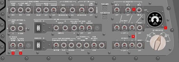
Two three-phases AC-busses provide the AC-load of the CSM. Three inverters (INV), powered from the MAIN BUSSES, generate 115 VAC at 400 Hz. INV 1 is powered by MAIN A, INV 2 by MAIN B, INV 3 can be powered by MAIN A or MAIN B. Only one INV can be connected to an AC-BUS at a time. DC-Power to the INVs is controlled by the switches in the upper row of the AC INVERTER-group 3.K. In the MAIN A (B)-position, DC-power from the selected MAIN BUS is fed to the INV. In OFF, DC-power is cut off. As INV 1 and 2 are only powered by one bus, they have two-position-switches. INV 3 has a 3-position-switch for putting it on either MAIN BUS.
AC-output of the INVs is controlled by the AC BUS 1(2)-switches 3.M. In ON (up), the respective INV is tied to the AC BUS. OFF disconnects the INV from the bus. Only one INV can power an AC-BUS at a time, so the INVs are interlocked against each other. When INV 1 is connected to the bus, INV 2 is disconnected automatically and cannot be connected. When INV 2 is connected to the bus, INV 3 is disconnected automatically and cannot be connected. When INV 3 is connected to the bus, INV 1 is disconnected automatically and cannot be connected. An overtemperature in an INV will trigger the INV 1(2,3) TEMP HI C&W-light and a master alarm.
The most right RESET-switch in each row controls the over- undervoltage and overload sensing unit of the respective bus. In center, the sensing unit is armed and will trigger the AC BUS 1(2) OVERLOAD C&W-light and a master alarm when an overload on the bus occurs. In the case of an under- or overvoltage, the AC BUS 1(2) and a master alarm will be triggered. An overvoltage will also trigger a disconnect of the INV powering this bus. RESET resets the sensing unit, extinguishes the C&W-light and reconnects the possible disconnected INV to the bus. OFF disarms the sensing unit.
The AC-voltmeter on MDC-3 can be put on each phase of each bus with the AC INDICATOR-selector below it. Normal reading is 115 +/-2 VAC.
Bat charger
BATs A, B and C can be recharged by the BAT CHARGER. The BAT CHARGER is provided with DC power from both MAIN BUSSES and with AC power from one of the AC BUSSES. The BAT CHGR switch 5.C selects the AC bus powering the BAT CHARGER.
By setting the BATTERY CHARGE selector 3.J to A, B or C, power is connected to the BAT CHARGER and the output of it is connected to the selected BAT. BAT A can only be recharged, when the MAIN BUS TIE BAT A/C switch is in OFF. BAT B can only be recharged, when the MAIN BUS TIE BAT B/C switch is in OFF. For recharging BAT C, both MAIN BUS TIE switches have to be in OFF. This assures that the recharged BAT carries no loads. Furthermore, when BAT A or B is recharged, the BAT RLY BUS – BAT A or B cbs should be opened to isolate the BAT from the loads on the BAT RLY BUS.
Output voltage and amperes of the BAT CHARGER can be monitored by setting the DC INDICATOR selector to BAT CHARGER. When the selector is in BAT CHARGER, the inner scale of the DC AMPS meter is valid (0 to 5 amps). When the output voltage reaches 39.8 volts, the BAT is fully recharged and the BAT CHGR selector should be set back to OFF.
Pyro bats
Each PYRO BAT supplies its PYRO BUS via the PYRO A (B) SEQ A (B) cb. In case of a failed PYRO BAT it is possible to connect BAT BUS A (B) to PYRO BUS A (B) by closing the BAT BUS A (B) TO PYRO BUS TIE cb. Before this, the PYRO A (B) SEQ A (B) cb has to be opened, otherwise one or both (PYRO)BATs will be damaged.
<biblio force=false> I Parameters are: H2 flow rate > 0.161 lb/h; O2 flow rate > 1.276 lb/h; pH Factor of exhaust H20 above 9 (pH HI tb barberpole); skin temp below 360°F or above 475°F; condenser exhaust temp below 150°F or above 175°F; radiator outlet temp < -30°F (FC RAD TEMP LOW tb barberpole) </biblio>