Future Expansion
There are plenty of candidates for future additions to the spacecraft simulated in Project Apollo after the basic historical Command/Service Module and Lunar Module are complete.
Spacecraft
Command/Service Module
Support may be added for the proposed Block-III CSM designed for extended orbital operations, the Block-IV CSM with batteries for power and LEM engines in place of the SPS and the Block-V intended for long duration lunar missions with one fuel cell replaced by two SNAP-27 RTGs.
In addition, the inclusion of a Block-I CSM in future versions has been discussed.
CSM Ferry

In 1965, NASA considered the possibility that the Saturn V could not be 'man-rated' in time to permit a lunar landing in the 1960's. Had this occurred an alternative mission profile was developed. An unmanned CSM/LM stack would be launched into orbit atop a Saturn V. Then a manned CSM ferry fitted with a drogue docking unit would be launched atop a Saturn 1b. The ferry would rendezvous and dock with the CSM/LM stack and after a crew transfer be jettisoned prior to the TLI burn.
See:
Apollo launch-vehicle man-rating. Some considerations and an alternative contingency plan.
Beyond Apollo: RAND's Apollo backup plan
CSM Shuttle

In 1967 North American Rockwell patented a proposal to turn the Apollo CSM into something resembling a miniature space shuttle with a payload bay in the Service Module, fins on the rear, retractable wings in the bottom of the SM, and X-15 style landing gear with a nose-wheel at the front of the SM and skids at the rear:
"An aerospace vehicle comprising a substantially conical forward crew compartment or command module mated to a substantially cylindrical rearward service module. Aerodynamic fairings are provided along the midline on the sides of the cylindrical portion and a substantial distance aft thereof for providing lift at hypersonic velocities and approximately vertical fins are provided on the fairings for aerodynamic stability and control. Wings are mounted within the aerodynamic fairings at high velocities and pivotably extended therefrom at lower velocities and altitudes to provide low speed lift."
This is explained in detail in US Patent 3,576,298.
Command/Cryogenic Service Module

In 1964 NASA conducted a preliminary study into using the RL-10 engine which powered the S-IV stage to provide power for the SM. The resulting Cryogenic Service Module would also have carried the fuel for the LM (as it was planned at that time), thus saving weight during launch.
See:
1. Analysis of a Cryogenic Service Module for the Apollo mission.
2. Advanced pressurization systems for cryogenic propellants. Final report, 20 Nov. 1963 - 25 Jun. 1965
Multi-Mission Module


In 1964 the Marshall Spaceflight Center patented the design of a booster stage that was intended to be the basis of a series of different spacecraft. In the illustration shown two such modules form the basis of a lunar logistics spacecraft.
One proposed alternative use would have seen the modules used as a replacement for both the Service and Lunar modules for the Apollo missions.
See:
1. Cryogenic Service Module Development Study
2. Comparative Design Study of Modular Stage Concepts - Volume III, Development Plans & Cost Analysis
Recycled/Renovated Command Modules

In 1966 North American/Rockwell proposed to NASA that recovered CSMs should be returned to the manufacturer for re-use, this ranged from a simple renovation of the Command Module to permit it to be re-launched in a future mission, to converting it into an experiment station/airlock for use on Apollo Applications flights.
See:
1. Renovated Command Module Laboratory and renovated command module study Final review
CM Parawing

In the late 1960's NASA studied the possibility of replacing the parachute based Earth Descent System with a parawing based system, allowing for the possibility of bringing the Apollo CMs down on land rather than at sea.
See:
4. Inertia tests of a 24 foot single keel parawing, model 2
CM Land-Landing System

One proposal for the later Apollo Extension/Apollo Applications missions was to equip the CM with a modified heat shield that would allow the CM to come down on land rather than in the ocean.
See:
1. Mechanical Impact System Design for Advanced Spacecraft (MISDAS). Phase I - Design concept selection
2. Mechanical Impact System Design for Advanced Spacecraft (MISDAS). Final Report
3. Mechanical Impact System Design for Advanced Spacecraft (MISDAS). Application to AES SPACECRAFT
Apollo Logistics Spacecraft

This was an Apollo CSM modified to carry freight and six astronauts into orbit in support of Earth orbital Apollo Applications Program missions.
The proposed craft, like the Block IV CSMs planned for the Apollo to Venus mission replaced the fuel cells with batteries and the SPS with a single LM descent engine
Proposed launch vehicles included the Titan IIIc or Saturn Ib.
See: MODAP (1963)
CSM Experiments Pallet

Proposed modification of the Service Module to permit a variety of Earth/Lunar orbit experiments to be carried. One such experiment set evolved into the Apollo Telescope Mount fitted to Skylab.
In a more limited form, this modification saw light as the SIM bay on Apollo 15-17.
See: Apollo Telescope Mount Study Program, Final Report
Lunar Shelter

North American/Rockwell patented a design for a Lunar Shelter which would use a Command Module and a Lunar Module descent stage to provide long-term accomodation for lunar astronauts on extended stays. Since there was no ascent stage, the Lunar Shelter could carry more supplies and provide more comfortable accomodation than an ascent-capable LEM. The astronauts would use their own LEM to return to orbit, which would be left on the surface in a 'hibernation' mode until the end of their stay.
LM/Apollo Telescope Mount


In the original Skylab plan the Apollo Telescope Mount (ATM) was to be attached to a modified LM ascent stage and launched into orbit aboard a Saturn Ib separately from an Apollo CSM carrying the Skylab crew. After a docking and crew transfer the LM/ATM would be docked with the Skylab station.
Two configurations were considered for the mission. The first was the Apollo Solar Telescope, the second was a set of instruments designed to study high-energy deep-space phenomena.
See:
1. Summary Description of the AAP Apollo Telescope Mount
2. Proposed payload for ATM-B for observing high-energy celestial sources
Nuclear-Ion, Lunar Logistics Spacecraft


Proposed Saturn INT-21 launched Nuclear-Ion propelled Lunar Logistics Vehicle, intended to support the post Apollo manned lunar base.
Several flight modes were envisaged. Firstly, after reaching the moon the vehicle would separate and the cargo module would land on the lunar surface leaving the power-plant in lunar orbit. Alternatively the power-plant would return to Earth orbit for re-use.
Consideration was also given to landing the complete spacecraft on the lunar surface where the power-plant would be used to provide electrical power for one of NASAs planned moonbases.
Finally a modified version of Lunar Orbit Rendezvous was considered in which the logistics vehicle (carrying the lunar lander) would be launched some months ahead of the Apollo CSM. The two spacecraft would meet in lunar orbit and then carry out an extended period of surface exploration.
HL-10 Lifting Body

The HL-10 was one of several experimental lifting bodies tested by NASA around the time of the Apollo program. At several points it was proposed that Saturn series rockets be used to orbit the spacecraft. The Saturn Ib was considered intially, later it was proposed that a Saturn V/Apollo CSM combination be used to orbit the vehicle with one of the Apollo crew returning the lifting body to Earth.
See:
3. Developing & Flight Testing the HL-10 Lifting Body
Emergency Escape Device

A small capsule launched on a Titan/Agena booster which could be used to rescue the crew from an Apollo Applications Program-based space station in Earth Orbit, or permanently attached to such a station as a lifeboat.
See:
1. Emergency Earth Orbital Escape Device Study Vol 1. Condensed summary
2. Emergency Earth Orbital Escape Device Study. Volume 2A. System requirements and concepts
3. Emergency Earth Orbital Escape Device Study. Volume 2B. Spacecraft system design
4. Emergency Earth Orbital Escape Device Study. Vol 2C. Reentry Controls
6. Emergency Earth Orbital Escape Device Study. Vol 2E. Additional study tasks
7. Emergency Earth Orbital Escape Device Study Vol 4. Apollo Applications
Orbital Escape Device

In 1967 NASA patented an inflatable orbital escape pod which could be carried mounted externally on the Service Module. In the event of a situation similar to the one described in the film Marooned, the crew would simply carry out an EVA, don the pod and use the attached solid rocket to deorbit.
An orbital escape vehicle which can be folded and stowed aboard an earth orbiting, manned spacecraft and used to safely return a crewman to the earth's atmosphere in the even of an emergency. The vehicle is comprised of a flexible casing having an ingress-opening therin, a heat ablative means covering said casing, and an inflatable bladder system within said casing for supporting the crewman and for maintaining said casing in a stable aerodynamic shape during its reentry into the atmosphere.
See: US Patent 3,330,510, US Patent 3,330,510 at the NTRS
LLRV/LLTV

The Lunar Landing Research Vehicle (LLRV) and later the Lunar Landing Training Vehicle (LLTV), humorously referred to as "flying bedsteads", were created to study and analyze piloting techniques needed to fly and land the tiny Apollo Lunar Module in the moon’s airless environment.
The LLRV is already available at Orbithangar using Vinka's Spacecraft.dll. More information can be found here: [1], [2], [3]

Later the LLTV was used. The LLTV incorporated changes that were the result of the initial LLRV test program and their systems were more like that of the real LM. More information can be found here: [4], [5], [6]
Lunar Mobility Aids
Lunar Motorbike

Little information is available, but the 'lunar motorbike' is variously claimed to have been designed as a backup in case the LRV wasn't finished in time for Apollo 15, or planned for use on Apollo 20 in addition to or as a replacement for the LRV.
Local Scientific Survey Module (LSSM)

Boeing's original design for what later became the LRV, the LSSM was a six wheeled vehicle designed to carry two astronauts and their equipment. Intended for the Dual-Apollo missions the LSSM would have been carried to the Lunar surface aboard an unmanned logistics vehicle to await the arrival of the Astronauts. It was intended to carry at least one Astronaut and 320kg (700 lb) of equipment on round trip excursions of up to 26km.
See: Preliminary design study of a lunar Local Scientific Survey Module (LSSM)
Bell Aerospace One Man Lunar Flying Unit

Simple one manned rocket, using the remaining fuel from the LM descent stage. It was intended for scouting missions within a maximum range of 15 miles from the landing site. Could be landed either with a manned lunar mission or via an unmanned logistics vehicle.
North American/Rockwell One Man Lunar Flying Unit

Simple one manned rocket, designed by North American/Rockwell, using the remaining fuel from the LM descent stage. It was intended for scouting missions within a maximum range of 4.6 miles from the landing site. Could be landed either with a manned lunar mission or via an unmanned logistics vehicle.
Long-Range Flyer

Simple two-man rocket using fuel from the LEM. This could be used for scouting missions to sites up to around 50 miles from the main landing site, or, in an emergency, to carry two astronauts from the lunar surface to rendevouz with the CSM.
Lunar Escape System

The Lunar Escape System was a simpler folding rocket than the Long-Range Flyer, which would be carried in the descent stage of the LM to allow the astronauts to fly into an orbit where the CM Pilot could recover them in the event that the ascent stage failed to fire.
To save weight, the fuel tanks would be inflatable and a set of detachable legs would be used purely for launch, then left behind on the Moon. No life-support facilities would be included other than the astronauts' suits, and there would be no automated guidance; the astronauts would fly to orbit manually using a pre-programmed pitch program and lunar landmarks. Propulsion would be provided by a collection of CSM/LM RCS thrusters.
Moonbases

 |{{#if:|, | and }}[[{{{2}}}|{{{2}}}]]}}{{#if:
 |{{#if:|, |, and }}[[{{{3}}}|{{{3}}}]]}}{{#if:
 |{{#if:|, |, and }}[[{{{4}}}|{{{4}}}]]}}{{#if:
|, and [[{{{5}}}|{{{5}}}]]}}{{#if: | (too many parameters in {{mainarticle}})}}
During the 1960's and early 1970's NASA had several plans for quasi-permanent surface or orbital Moonbases to serve as the climax to the Apollo program.
Projects and Missions
Original Saturn plans


The original Saturn-A, -B, -C and Nova designs, possibly including the earlier lunar landing plans based on multiple launches, or the single launch putting the entire CSM onto the Moon using the massive Saturn C-8 booster.
For more information see, for example, Saturn family and Nova family at Astronautix.com.
See:
1. A study of large launch vehicle systems for a manned lunar landing program
2. Direct Flight Schedule and Feasibility Study for Project Apollo
3. Manned Lunar Landing Program Mode Comparison
4. Picture of the Saturn C-8 with stage dimensions.
AAP Mission 1a


Planned Earth Resources study using instrumentation mounted on a carrier bus that would be placed into a 260-280km orbit using a Block II CSM and a Saturn 1b.
A modified version of this carrier was planned to be used as a resupply vehicle for the AAP version of Skylab
See:
Technical Data AAP Mission 1a, 60 Day Study
Apollo to Venus

Phase B of the Apollo to Venus plan called for the addition of solar panels to the 'wet workshop' and the use of a Block III CSM so that the astronauts would fly the SIVB into a high altitude orbit for a year-long mission in preparation for an actual fly-by.
Phase C of the Apollo to Venus plan would use an improved version of the 'wet workshop' SIVB with a Block-IV CSM to perform the actual Venus flyby.
Wikipedia has some more information.
AAP Venus Flyby Mission


Another proposal for using Apollo hardware to study Venus involved the replacement of the LM with a Mission Module which would serve as the crew quarters during a year long Venus flyby mission.
The spacecraft would be launched by a standard Saturn V with the S-IVb injecting the CSM/MM into a two day elliptical orbit with the SPS providing the thrust for Trans-Venus Injection.
See:
1. Preliminary mission study of a single-launch manned Venus flyby with extended Apollo hardware
2. Beyond Apollo - Piloted single-launch Venus flyby (1967)
Apollo/Salyut/Soyuz Test Project

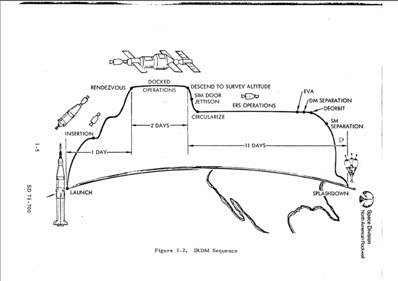
Early in the planning for the Apollo-Soyuz Test Project, consideration was given to have the Apollo dock with a Salyut space station to carry out the joint mission. After two days of mutual operations the Apollo would undock and carry out an Earth Resources survey of the United States before splashing down one fortnight after launch.
This wouldn't require much of a change, since the ASTP docking module should be able to dock with either: it would primarily require new scenarios and both Soyuz and Salyut from other add-ons. Furthermore, the CSM used for this mission was essentially in the J-Class configuration with SIM bay instruments, so models and animations from Apollo 15-17 could be used to represent the ASSTP Apollo.
See: Flightplan
Satellite Rendezvous and Refurbishment Missions


In 1967 it was proposed that NASA assign three AAP missions to studying the repair of satellites in space.
Each mission would see a Saturn Ib launch a CSM and a special capture mechanism into a 370km (200nm) orbit. After transposition and docking the CSM would rendezvous with one of the Orbiting Solar Observatory(OSO) series of satellites and perform a series of EVA space maintenance experiments.
In the first mission, proposed to take place in December 1969, after capture of the satellite an astronaut would remove parts of the spacecraft instrumentation for return to Earth, before refueling the pitch control system.
The second mission would take place a year after the first, in this mission after spacecraft capture, the astronaut would, in addition to refueling the spacecraft pitch & spin control systems, install replacements for the spacecrafts battery and data recording systems.
The final mission would take place two years after the first. After docking with a failed OSO an astronaut would carry out a spacecraft refurbishment similar to that from the second mission. In addition spacecraft experiments would be replaced as would specific components in the spacecraft control system.
See:
1. Experiments for satellite and material recovery from orbit. Volume I - Summary Final report
2. Experiments for satellite and material recovery from orbit. Volume II - Technical Final report
4. OSO Spacecraft Manual, Revised for OSO-D
High Orbit Laser Communications Test

To provide a possible alternative to using radio links for interplanetary communications Perkins-Elmer, a firm later involved in the construction of the Hubble Space Telescope was asked to design a laser communications system. By 1966, their work was sufficiently advanced to propose that NASA set aside an Apollo mission to test out their planned system.
A Saturn V would launch an Apollo CSM & LM into synchronous orbit where the tests were to take place. Perkins-Elmer evolved five different concepts for carrying out the communications tests, three involved using modified LMs to carry the combined laser communications unit/telescope into orbit.
High Orbit Optical Systems Experiment

A plan to place in synchronous orbit a LM whose descent stage was replaced with an optical array for the purpose of testing various advanced optical systems, such as segmented mirrors, communications lasers and stellar interferometry.
Large Telescope Experiment Program (LTEP)

As part of the development process that led to the Hubble Space Telescope, it was proposed to launch a prototype telescope on the second Skylab OWS.
See:
1. Large Telescope Experiment Program (LTEP). Executive Summary
2. Large Telescope Experiment Program (LTEP), Vol. 1, Part 1.
3. Large Telescope Experiment Program (LTEP), Vol. 1, Part 2.
4. Large Telescope Experiment Program (LTEP), Vol. 2, Part 1.
5. Large Telescope Experiment Program (LTEP), Vol. 2, Part 2.
Erectable 15ft Parabolic Antenna


Convair proposal to mount an erectable 15ft parabolic antenna to the AAP Orbital workshop. It's intial experimental purpose would be to test the operational characteristics of the antenna and the effects of space exposure to those characteristics, there-afterwards it would be used as the primary transmission antenna for the Orbital Workshop.
Large erectable antenna for space application, Final report
High Orbit Interferometer Test

In 1966 NASA asked Convair to research the use of Apollo systems to test out large scale space construction projects. One of the possible large scale space experiments studied was the deployment into synchronous orbit of a radio interferometry satellite which after the initial series of experiments could be visited by a future Apollo spacecraft and placed into a new orbit for for further observations.
Orbital X-Ray Telescope

In 1966 NASA asked Convair to research the use of Apollo systems to test out large scale space construction projects. One of the proposals involved the use of a Saturn Ib to place a 30in (76 cm) diameter X-Ray telescope into a 260nm (480 km)high orbit.
High Orbit Parabolic Antenna Test

In 1966 NASA asked Convair to research the use of Apollo systems to test out large scale space construction projects. One such project was the use of a Saturn V/CSM combination to deploy a 100ft Parabolic Antenna into a synchronous orbit so that the characteristics of the antenna could be determined under operational conditions.
Little Joe 2 Suborbital Test Flights

The original Little Joe 2 test program included not only the Launch Escape Tests, but also suborbital tests of the Service Propulsion System and Lunar Module.
Mars Excursion Module Testing


To ensure the success of the Mars landings planned for the Integrated Manned Programme North American/Rockwell proposed that NASA use Saturn/Apollo derived hardware to test the Mars Excursion Module.
Unmanned missions included the use of an S-Ic stage to lob an MEM into the Atlantic for a test of the re-entry ballute system, along with the creation of a Little Joe III launch vehicle for descent abort testing. Unmanned testing would culminate in an unmanned re-entry from Earth Orbit.
Manned testing would consist of two missions, firstly, a test of the descent/ascent propulsion system similar to that carried out by Apollo 9 and then a manned re-entry test. Another option that North American/Rockwell considered was to place an MEM in lunar orbit and have the crew of an Apollo CSM rendezvous with it. This crew would then use the MEM to land on the lunar surface, conduct a brief period of exploration before returning to Earth in the CSM.
See: Definition of Experimental Tests for a Manned Mars Excursion Module, Vol. 4: Briefing
Orbiting Primate Spacecraft

NASA's long term mission plans involved space-voyages lasting for several years. While Apollo would provide some information on the effect of weightlessness on the human body over short periods of time, the full effects of longer periods was considered an especial concern.
To study the effects of weightlessness over long periods, it was proposed that during the Apollo Applications program a spacecraft carrying two monkeys would be boosted into a 463km (250 nm) orbit using an Apollo CSM. After a year in orbit the monkeys would be returned to Earth by another CSM.
Passive Communications Satellite Test

Apollo Applications studies covered a wide range of subjects, from Post-Apollo lunar exploration to Earth-Orbiting space stations. One study carried out by Goodyear looked at using Apollo to test a Passive Communications Satellite, in furtherance of the research carried out using the Echo satellites.
The un-inflated satellite would be launched aboard a Saturn V and would be deployed at an altitude of 500 miles (805 km)using an Apollo CSM. After inflation and testing the Apollo crew would EVA to retrieve film cameras aboard the satellite and the S-IVb stage prior to re-entry.
This one should be fairly easy to do, as it is essentially an extension of the Apollo 7 manned mission and related models exist as part of the Apollo to Venus Phase A mission.
Perhaps of further interest is the similarity between the Goodyear satellite and some configurations of the Project Able Mirror.
Project Able LEM

A plan to use a mirror in space to light up parts of the Vietnam jungle at night. A modified LEM with a huge flexible mirror attached would be launched into a 28.5 degree synchronous orbit hovering over 105.5ºE where the mirror would unfold.
A similar plan proposed using a modified LEM to fly to Soviet satellites and spray paint over their sensors: the first space vandals.
Lunar Photo-Mapping LEM


In 1963 it was proposed that the LM be modified to carry out a lunar photo-mapping mission before the first manned landing.
The cameras would either have been mounted in place of the surface EVA hatch or in an extension to the ceiling of the Ascent Module.
The descent module would have it's legs removed and replaced with a set of eight drop probes for the study of the lunar surface.
See: Study Of LEM For Lunar Orbital Reconnaissance
Project Icarus
Proposal to divert or destroy an incoming asteroid by launching 100 Megaton nuclear bombs on Saturn Vs.
See:
1. The Space Review: Giant Bombs on Giant Rockets
2. Beyond Apollo: Project Icarus(1967)
3. Systems Engineering: Avoiding an Asteroid (16 June 1967)
4. MitPress Catalog, The Project Icarus Report
Project Horizon
Project Horizon, was a proposed US Army plan written up by Von Braun, it would have used multiple Saturn I (Saturn-A1) and Saturn II (Saturn-B1) launches to establish a 12 man army post on the moon.
See:
Project Horizon Report: Volume I, Summary and Supporting Considerations
Project Horizon Report: Volume II, Technical Considerations & Plans
Lunex Project

The Lunex Project was a proposed US Air Force alternative to Apollo, which would use a lifting-body re-entry vehicle and land the entire spacecraft stack on the Moon rather than having a separate lander which rendezvoused with the orbiting return craft.
See: LUNEX (1961)
Unmanned Spacecraft
During the lifetime of the Apollo Program the Saturn launch vehicles were considered for use as unmanned satellites and probes, most famously the Voyager Mars probes.
High Orbit Nuclear Powered Television Satellite

NASA's SNAP program was a study into the use of small nuclear power-plants in space. One strand of this research resulted in the Radio-Thermal Generators (RTGs) carried aboard the Apollo, Viking & Pioneer missions. Another looked into the creation of small nuclear reactors that could be launched 'cold' and then started up in orbit.
One proposed use for these reactors was to power a Television Satellite that would be placed into a synchronous orbit by a Saturn V.
See:
1. SNAP-8 Performance Potential Study, Final Report
2. SNAP-8 electrical generating system development program
Advanced Mars Probe


In mid 1967 a group of University of California students working in a NASA sponsored course designed a Mars Probe launched by a Saturn V/Centaur.
With a proposed launch date in 1977, the probe would have carried a rover designed by McDonnell-Douglas along with a powerful multi-spectral camera and laser altimeter to the Red Planet.
See:
Jupiter Orbiting Vehicle for Exploration (JOVE)


During the 1960's NASA sponsored a number of university engineering courses covering the design and planning of robotic exploration. The engineering students of the University of Auburn (Alabama) designed a Jupiter orbiter using equipment designed for both the Apollo and Voyager Mars programs.
Launched by a Saturn V in either 1978 or 1980, the probe was to be inserted into an elliptical polar orbit and study the planet for 100 days.
See:
JOVE, Jupiter orbiting vehicle for exploration. Volume 1 - Mission and system study, Final report
JOVE, Jupiter Orbiting Vehicle for Exploration. Volume 2 Appendixes, Final report
Jupiter Orbiting Spacecraft (JOSÉ)


During the 1960's & 70's NASA sponsored a number of university engineering courses covering the design and planning of robotic exploration. Students from Cornell University designed a Jupiter orbiter intended to be launched by a INT-20/Centaur in November 1980. After reaching Jupiter in July 1982 it would spend three years studying the planet.
See:
JOSÉ, Jupiter orbiting spacecraft: A systems study, volume 1
Smithsonian Earth Physics Satellite (SEPS)


In the aftermath of the Skylab Program consideration was given to using left over Saturn hardware to place a 3.6 ton retro-reflector equipped geodetic satellite into a high stable orbit.
See: The Smithsonian Earth Physics Satellite (SEPS), Definition Study, Volumes I - III
Launch Vehicles
Little Joe 2

The Little Joe 2 was a solid rocket booster designed by General Dynamics/Corvair, it was used to gather flight test data on the Apollo Launch Escape and Earth Landing systems.
Saturn C-2 MLV

Proposed version of the Saturn C-2 rocket with a first stage formed from a cluster of SRBs. Capable of carrying 60,000 pounds into orbit or 18,500 pounds into an escape trajectory.
The same study also proposed a second vehicle capable of putting 130,000 pounds into orbit. This was a four stage rocket comprising a 16 SRB first stage, a 4 SRB second stage, an augmented S-II stage with six J-2 engines as a third stage and an S-II derived fourth stage fitted with two J-2 engines.

Saturn 1


The Saturn 1 was the precursor to the Saturn 1b, using an SIV stage in place of the SIVB. The SIV was smaller, with a lower fuel capacity, and used multiple RL10 engines in place of the J2 engine on the SIVB.
NASA also considered recovering the first stage of the Saturn I with a paraglider and conducted a few preliminary model tests.
See:
3. Application of Paragliders to S-1 Booster Recovery for C-1 and C-2 Class Vehicles
4. Paraglider Recovery System for the Saturn Booster
5. Candidate materials for Saturn paraglider recovery system
Saturn 1b/Centaur

Briefly known as the S-V stage the Centaur high energy booster formed part of many of the early Saturn rocket plans. Later on it was planned to fit a Centaur stage onto a standard Saturn Ib, forming a launch vehicle capable of sending a 4.4 metric ton payload on a flyby mission to Mars.
Saturn 1b MLV

As part of NASA's cost-cutting plans, they studied a 'Modified Launch Vehicle' (MLV) derivative of the Saturn 1b which would replace the S1B stage with a solid rocket that was twice the diameter of a shuttle SRB and possessing one and a half times the thrust. In essence this was a 1960s version of NASA's new 'Stick' launcher for the CEV.
See: Astronautix
See: Astronautix for details of the engine that would have been used.
Saturn 1b with multiple SRBs

Other Saturn 1b proposals would replace the S1B stage with multiple SRBs, or simply attach SRBs to the side of the S1B stage for extra thrust: that would increase payload rather then reduce cost.
Some other Saturn designs were proposed using multiple large SRBs for the first stage; one even utilising two S-II stages, one stretched with extra propellant the other using two engines rather than five.
Saturn 1 RIFT and Saturn V/Nuclear

.png)
.png)
.png)
NASA planned to develop a Nuclear-Thermal rocket stage to act as a high-energy booster for the Saturn series.
Two nuclear stage designs were considered for the initial RIFT program, firstly, a prototype stage, equivalent to the S-IV stage on the Saturn 1 would have been 23.47 (77ft) by 660cm (260in) and produced (54,500lb) of thrust. This would have allowed the Saturn 1/N test vehicle to place 15,000kg (32,795lb) into a 160-480km (100-300mi) orbit.
The production stage, was the equivalent of the S-IVb stage and was intended to be used as the third stage of a Saturn II, Saturn III or Saturn V launch vehicle. With dimensions of 29m (94ft) by 660cm (260in) and producing (80,900lb) of thrust this would have enabled the Saturn II to send a 22,000kg (47,500lb) probe to the Moon or a 20,000kg (43,000lb) probe to Mars.
Fitted to a Saturn V the production stage would have enabled the launching of a 72,000kg (159,000lb) payload directly into a lunar trajectory or a payload of 71,000kg (156,000lb) using the Apollo launch profile (TLI from 160km (100mi) parking orbit).
See:
1. Reactor in-flight test system. Volume 1: RIFT program summary
2. RIFT S-N stage inertial systems preliminary conceptual design report
3. RIFT S-N Stage flight control system conceptual design report
Saturn INT-21

Two-stage launcher used to launch large payloads into Earth orbit. This was used for the Skylab mission.
See: Astronautix
Saturn V/J-2S

A Saturn V modification where the S-II & S-IVb stages are fitted with J-2S Engines. These uprated versions of the J-2 would have allowed for increased payloads on lunar missions, given the S-IVb a three restart capability for synchronous orbit missions & allowed the S-II stage to carry out orbital circularization when used as part of a Saturn INT-21.
This is probably the simplest of the Apollo modifications to implement in NASSP requiring only a change in the thrust parameters of the J-2.
See:
1. J-2S Improvement Study, Summary
2. J-2S improvement study, Systems Description
3. Comments on the J-2S engine impacting on the Saturn 5 program
4. Study of J-2S engine impact on Saturn 5 launch operations
Saturn S-ID stage
A modified S1C stage which dropped the outer four engines in a similar manner to the Altas dropping two of its engines during launch. As well as multi-stage launchers with greater payloads, it could carry 50,000 pounds to low orbit itself with no second stage.
See Astronautix.
Saturn S-IVC stage

A modified S-IVB which would be optimised for use in interplanetary missions. A manned flyby of Mars, for example, might use a stack of three S-IVC stages to launch the flyby spacecraft from Earth orbit.
See:
Saturn Cryogenic Planetary Injection Module

A proposed fourth stage for the Saturn V which would have used either Hydrogen or Fluorine based propellants for interplanetary & lunar logistics missions.
See: Preliminary Design of a Cryogenic Planetary Injection Module
See: Other Mission Applications for a Cryogenic Planetary Injection Module
Saturn V-24
Saturn V with stretched stages, new toriodal aerospike engines on the upper stages, uprated F-1 engines on the first stage, and four strap-on boosters with two F-1 engines each. Capable of putting over 500,000 pounds of payload into low Earth orbit.
Skylab and Alternative Space Stations
Skylab

The NASSP 5.x Skylab sources were lost, so a new version will be required once the INT-21 support is added.
AAP Skylab

By 1968 the NASA plans for what became known as Skylab reached their final pre-Apollo Lunar Mission form. There would be eight Saturn 1b launches (two unmanned) and missions would last from 28 to 56 days.
In 1969 Hollywood took these plans and used them as the basis for the SF thriller Marooned.
Interim Orbital Workshops

In 1971, NASA briefly looked at launching four additional Orbital Workshops after Skylab I both as a means of keeping manned spaceflight experience intact and of testing a variety of different spacecraft power systems. Launched by a Saturn INT-21, the stations would test out Solar Power, RTG power and a fully operational nuclear reactor in orbit.
Logistics support for the stations, until the space shuttle could come on line would be three or four man Apollo CSMs launched by Saturn Ibs, Saturn Ib MLVs and Titan IIIms.
Orbital Launch Facility

At the same time as the Air Force was planning its Manned Orbital Laboratory, NASA was presented with a civilian version called the Manned Orbiting Research Laboratory (MORL).
As part of NASA's post moon-landing plans, Boeing was asked to design a space station that could be used as an Orbital Launch Facility (OLF) for lunar ferry missions in support of a permanent Lunar base and manned missions to Mars and Venus.
The OLF was a nuclear powered cylindrical station built around two MORLs joined back-to-back and could be launched by a single Saturn INT-21. The station would be supported by two craft, the manned Apollo Logistics Module, a CSM modified to carry a six-man crew and logistics cannisters and an unmanned fuel tanker which would carry the fuel used by the modified S-II stage, which boosted the lunar ferries and manned expeditions out of Earth Orbit.
Baseline Orbital Workshop


The original Skylab plan envisaged launching the CSM and Orbital workshop atop a single uprated Saturn 1b into a 148.4km high orbit. After launch the CSM would separate from the S-IVb and dock with the Airlock Module (AM) that replaced the LM atop the S-IVb stage.
Once the S-IVb had been purged of its remaining fuel, the SPS would be fired to place the CSM/AM/S-IVB combination into a target orbit anywhere between 277 - 370 km with an inclination of between 28 - 50 degrees. Once in the planned orbit the astronauts would use the hydrogen tank as additional living space while in orbit.
The intended mission payload was a series of Earth resources experiments attached to the Airlock Module and looking outward past the docked CSM.
Power for the 30 day mission was to be supplied by the CSM fuel cells, with the additional reactants being carried aboard the AM.
The Phase A mission of the Manned Venus Flyby intended to use an identical spacecraft configuration.
Boeing Single Launch Space Station Proposal


During the 1960's NASA and the companies working with it studied a number of different space station designs for the follow up to the AAP Skylab project.
Boeing looked at a design that would be, like Skylab launched as a single unit atop a Saturn INT-21. Starting with a four-deck design, Boeing determined that the best fit would be a two-deck space station the same diameter as the S-II stage on the launch vehicle.
The space station would support a 6 man crew for at least a year. They would be carried to and from orbit in 6 man Apollo derived logistics spacecraft. For use as lifeboats in an emergency two Apollo Command Modules fitted with de-orbit retro-packs would be attached to the station from launch.
Boeing also studied the possibility of using the space station mission to test out components and procedures for a manned flyby of Mars.
Self Deploying Space Station


In 1962 North American/Rockwell studied the possibility of building a rotating space station that could be launched into orbit in a stack comprising a Saturn V in the INT-21 configuration, the station itself and an Apollo CSM carrying a three man crew.
Once in orbit the station would be able to host up to 7 Apollo CSMs and a crew of 21.
Lockheed Modular Space Station

In 1965 Lockheed proposed to NASA that future space stations be constructed out of a common 460cm (183in) diameter building block designed to be mounted in the LM adapter of the S-IVb stage.
One use considered was to send an Apollo crew to Venus in a modified Apollo CSM linked to a single mission module.
Artificial Gravity Space Station
Proposed Saturn V INT-21 launched space station that would have used the spent S-II stage as a counterweight so that artificial gravity could be generated by rotating it and the crew module around a fixed hub. Two configurations were considered. The first, intended for a 9 man crew would have had the same diameter as an S-IVb stage.

The second planned configuration, which would have had a 24 man crew had the same diameter as an S-II stage.

Resupply of the stations would have been using Apollo CSMs modified into a logistics configuration.
SLA Workshop

Even as the basic design of Skylab was being finalized, an alternative design was created to enable the mission objectives to be fulfilled in a more economical fashion, should it become necessary to do so. Called the SLA Workshop, the alternate orbital laboratory was a conical vessel that would replace the CSM/SLA atop a Saturn 1b. Three variants were envisaged, one for earth resources observations, one to carry a solar telescope and finally, one carrying a standard astronomical telescope.
Integrated Manned Programme

 |{{#if:|, | and }}[[{{{2}}}|{{{2}}}]]}}{{#if:
 |{{#if:|, |, and }}[[{{{3}}}|{{{3}}}]]}}{{#if:
 |{{#if:|, |, and }}[[{{{4}}}|{{{4}}}]]}}{{#if:
|, and [[{{{5}}}|{{{5}}}]]}}{{#if: | (too many parameters in {{mainarticle}})}}
NASAs ultimate Post-Apollo plan, one which would have combined the Space Shuttle with Saturn Vs to put men permanently on the Moon and send them on to Mars and Venus.
References
Here are a selection of documents with information on these spacecraft, both historical and planned:
- US Army, Project Horizon, Volume One: Summary and Supporting Considerations June 9, 1959
- US Army Ordnance Missile Command, A Lunar Exploration Program Based Upon Saturn - Boosted Systems, February 1, 1960
- Reactor in-flight test system. Volume 1 RIFT program summary, March 1961
- S. Cloverdale, Design Studies Of Very Large Solid Rockets, Final Report, April 9, 1961
- Space Systems Division, Air Force Systems Command, Lunar Expedition Plan, May 1961
- The Apollo 'A' Saturn C-1 launch vehicle system, July 17, 1961
- R.P. Smith, Project Apollo - A description of a Saturn C-3 and Nova vehicle, July 25, 1961
- Jet Propulsion Laboratory, Some interrelationships and long range implications of C-3 lunar rendezvous and solid Nova vehicle concepts, October 1961
- A.G. Orillion & G.P. Pedigo, Apollo Launch Vehicle Design, January 1, 1962
- North American/Rockwell, Self Deploying Space Station, Interim Summary Report, Vol. 1, January 1, 1962
- L.M. Tinnan, E.A. Weber, Self Deploying Space Station, Appendixes, April 10, 1962
- A.I. Kaufmann Summary of Earth orbital rendezvous studies, July 1, 1962
- L.M. Tinnan, E.A. Weber, Self Deploying Space Station, Final Report, Scale Model Tests, 31 October, 1962
- Direct flight Apollo study. Volume 1:Two man Apollo spacecraft, October 31, 1962
- Direct flight study using Saturn C-5 for Apollo project. Volume 1 Summary, February 1, 1963
- J.H. Semcken, Feasibility study and detailed test plans for LEM-1 and LEM-2, September 6, 1963
- Nasa support manual - Apollo description manual applicable to boilerplate 6 only, October 25, 1963
- W.F. Dankhoff, The M-1 rocket engine project, November 1963
- Final Technical Presentation Modified Apollo Logistics Spacecraft, 1963
- Apollo Systems Description: Vol 2. Saturn Launch Vehicles, February 1, 1964
- Bell Aerosystems, LLRV Weight and Balance Handbook, April 1, 1964
- N.G. Huber, Post-Saturn launch vehicle study part II condensed summary report, April 10, 1964
- North American/Rockwell, Apollo Command and Service Module System Specification (Block I) (Updated), August 28, 1964
- Orbital Payload Potential: Saturn 1B Earth Launch Vehicle Using Solid Propellant Motors, September 1964
- J.L. Sanders, Advanced post-Saturn earth launch vehicle study executive summary report, February 3, 1965
- E.D Harris & J.R Brom, Apollo launch-vehicle man-rating. Some considerations and an alternative contingency plan., May 1 1965
- J.W. Larson, Electrically-propelled cargo vehicle for sustained lunar supply operations, Final report, June 28, 1965
- Modified Launch Vehicle MLV Saturn V Improvement Study Composite Summary Report, July 2, 1965
- Lockheed, Modular multipurpose space station study, Final Report. Section 1 - Introduction. Section 2 - Technical summary, July 30, 1965
- Lockheed, Modular multipurpose space station study, Final Report. Section 3 - Modular space station design, Part 1, July, 30, 1965
- Lockheed, Modular multipurpose space station study, Final Report. Section 4 - Preliminary specifications, July, 30, 1965
- Lockheed, Modular multipurpose space station study, Final Report. Section 5 - Multipurpose space station applications. Section 6 - Development plan, July, 30, 1965
- Lockheed, Modular multipurpose space station study, Final Report. Appendix - Experimental application summary Final report, July, 30, 1965
- J.J. Traxler, Saturn 1B Centaur propulsion systems compatibility study, August 6, 1965
- R.M. Croft, Utilization of an orbital launch facility for planetary missions, September 1965
- Orbit Launch Facility Study, VOLUME I Technical Report Summary Final, October 1965
- Orbit Launch Facility Study, VOLUME IIa Technical Report Final, October 1965
- Orbit Launch Facility Study, VOLUME IIb Technical Report Final, October 1965
- Orbit Launch Facility Study, VOLUME III OLF Study Research & Technology Implications Final Report, October 1965
- LEM utilization study for Apollo extension system missions. Volume VI - Schedule analysis Final report, October 15, 1965
- H.R. Lowery, Saturn instrument unit command system, October 22, 1965
- North American/Rockwell, Renovated Command Module Laboratory and renovated command module study Final review, January 1, 1966
- Saturn I Summary, February 15, 1966
- S.G. Embrey, The Apollo Saturn Emergency Detection System, February 17, 1966
- W.W. Hough, Apollo experiments pallet interim technical description, March 3, 1966
- Ball Brothers Research Centre, Apollo Telescope Mount Study Program, Final Report, April 1, 1966
- 260-in.-dia motor feasibility demonstration program Final program summary report, Jun. 1963 - Apr. 1966, April 8, 1966
- General Dynamics/Convair, Little Joe 2 test launch vehicle NASA Project Apollo. Volume 1 Management, May 1, 1966
- General Dynamics/Convair, Little Joe 2 test launch vehicle NASA Project Apollo. Volume 2 - Technical summary Final report, May 1, 1966
- W.W. Hough, Study of the Apollo experiments Pallet as a support system for orbital experiments, May 20, 1966
- International Business Machines, Saturn IB 5 instrument unit instrumentation system description (S-IU-2-02 through 204 501 through 503), June 1, 1966
- Preliminary design study of a lunar Local Scientific Survey Module (LSSM), June 1, 1966
- J.I. Ito, Development of LO2/LH2 Gas Generators for the M-1 Engine, June 1, 1966
- J.W. Larson, Electrically-propelled cargo vehicle for sustained lunar supply operations, Summary report, June 24, 1966
- Laser Communication Satellite Experiment (LCSE), July 1, 1966
- T.C. Tweedie jr, Installation of S-027 in the IU of Mission 209, July 21, 1966
- M.S.Feldman, Saturn ib modifications required to support the orbital workshop mission, August 1966
- Optical technology Apollo extension system. Part I - Presentation, September 27, 1966
- Optical technology Apollo extension system, Part I Summary report, September 27, 1966
- Optical technology Apollo extension system, Part I. Executive summary report, September 27, 1966
- Optical technology Apollo extension system, Part I. Volume I, Book 1 of 2. Final technical report, September 27, 1966
- Optical technology Apollo extension system, Part I. Volume I, Book 2 of 2. Final technical report, September 27, 1966
- Optical technology Apollo extension system, Part I. Volume II. Final technical report, September 27, 1966
- Optical technology Apollo extension system, Part I. Volume III. Final technical report, September 27, 1966
- Optical Technology Apollo Extension System. Part II - Definition of work tasks, September 27, 1966
- G.W. Craft, A.W. Starkey, Dock concept for handling and launching large solid rocket engines applied to Saturn IB-5A launch vehicle, September 30, 1966
- PasComSat Experiment for Apollo Application Program, October 1966
- E.W. Conrad, J.K. Curley & J.P. Wanhainen, Cooled baffle development for M-1 engine using a subscale rocket engine, October 1, 1966
- Final Report - Studies of Improved Saturn V Vehicles and Intermediate Payload Vehicles, October 7, 1966
- G.W. Craft, Saturn improvement studies A summary, October 28, 1966
- D.J. Belz, Summary description of the SAA airlock module, November 1966
- Preliminary technical data for earth orbiting space station. Volume I - Summary report, November 7, 1966
- Preliminary technical data for earth orbiting space station. Volume II - Standards and criteria, November 7, 1966
- Preliminary technical data for earth orbiting space station. Volume III - Systems, November 7, 1966
- Preliminary technical data for Earth orbiting space station. Volume IV - Configuration, integration and weights, November 7, 1966
- Multi-Mission Module - Patent, November 22, 1966
- Feasibility Study of Utilization of LM for Project Able - Vol. I - Technical Summary, December 12, 1966
- Feasibility Study of Utilization of LM for Project Able - Vol. II - Technical Report, December 12, 1966
- North American/Rockwell, Study of a renovated command module laboratory and renovated command module. Volume 1 - Summary Final report, December 15, 1966
- North American/Rockwell, Study of a renovated command module laboratory and renovated command module. Volume 2 - Mission system performance and configuration analysis Final report, December 15, 1966
- North American/Rockwell, Study of a renovated command module laboratory and renovated command module. Volume 3 - Subsystems analysis Final report, December 15, 1966
- North American/Rockwell, Study of a renovated command module laboratory and renovated command module. Volume 4 - Resources requirements analysis Final report, December 15, 1966
- G.W. Craft, Implementing Dock Launch of MLV Saturn 1B-5A, December 29, 1966
- C.C. Ciepluch, Status of the 260-inch diameter solid rocket motor program, January 1, 1967
- Manned Venus Flyby study, Feb. 1, 1967
- Preliminary considerations of Venus exploration via manned flyby, Nov 30, 1967
- North American/Rockwell, Definition of Experimental Tests for a Manned Mars Excursion Module, Vol. 4: Briefing, Nov. 1, 1967
- A Venus lander probe for manned flyby missions, Feb 23, 1968
- A survey of manned Mars and Venus flyby missions in the 1970s May 17, 1966
- Manned Venus flyby meteorological balloon system, July 29, 1968
- Experiment payload for manned venus encounter mission - venus tracking and data orbiter, Jun 13, 1968
- Drop sonde and photo sinker probes for a manned venus flyby mission , May 7, 1968
- J.D. Belz, Modified Saturn launch vehicles for AAP earth orbital missions, April 14, 1967
- Saturn 5 single launch space station and observatory facility, study contract - Midterm oral review, 14 June, 1967
- Motor 260-SL-3 program. Volume 2 - 260-SL-3 motor propellant development Final phase report, July 14, 1967
- Aerojet-General Corporation, The M-1 rocket engine project, Final Report, August 1967
- Optical technology Apollo extension system (OTES), phase A. Volume 6, section 6 - Resources analysis Final technical report, August 18, 1967
- L.T. Kail, Saturn S-4B workshop for manned, orbital animal research facilities - feasibility study, September 1 1967
- Optical technology Apollo extension system (OTES), volume 2 Final report, September 15, 1967
- Optical Technology Experiment System (OTES). Phase 2: LMSC input, September 15, 1967
- C.D. Harris and A.A. Luoma, Static longitudinal aerodynamic characteristics of a hammerhead-shaped Little Joe II - Lunar module model at Mach 0.30 to 1.20, October 1, 1967
- Optical technology Apollo extension system (OTES), volume 1, October 1 1967
- Optical technology Apollo extension system (OTES), phase A study Summary report, October 1, 1967
- Optical technology Apollo extension system (OTES), phase A, volume 3, section 3 - Experiments Final technical report, October 18 1967
- Saturn 5 single launch space station and observation facility. Combined mission concept evaluation Final report, November 1967
- Large space structure experiments for AAP. Volume 1 - Summary Final report, 15 Sep. 1966 - 15 Sep. 1967, 30 November 1967
- Large space structure experiments for AAP. Volume 2 - Analysis and evaluation of space structure concepts Final report, 15 Sep. 1966 - 15 Sep. 1967, 20 September, 1967
- Large space structure experiments for AAP. Volume 3 - Crossed-H interferometer for long wave radio astronomy Final report, 15 Sep. 1966 - 15 Sep. 1967, September 20, 1967
- Large space structure experiments for AAP. Volume 4 - Focusing X-ray telescope a large space structure for X-ray astronomy Final report, 15 Sep. 1966 - 15 Sep. 1967, 20 November 1967
- Large space structure experiments for AAP. Volume 5 - Parabolic antenna Final report, 15 Sep. 1966 - 15 Sep. 1967, 22 November 1967
- Northrop, Orbiting experiment for study of extended weightlessness. Volume 1 - Summary, December 1 1967
- Northrop, Orbiting experiment for study of extended weightlessness. Volume 2 - Systems Definition, December 1, 1967
- Northrop, Orbiting experiment for study of extended weightlessness. Volume 3 - Spacecraft preliminary design, December 1 1967
- Northrop, Orbiting experiment for study of extended weightlessness. Volume 4 - Laboratory test model, December 1 1967
- Northrop, Orbiting experiment for study of extended weightlessness. Volume 5 - Program plans, December 1 1967
- Northrop, Orbiting experiment for study of extended weightlessness. Volume 6 - Orbiting primate spacecraft applications, December 1 1967
- An Alternate Apollo Applications Program for Earth Orbit, January 1968
- Advanced Mars orbiter and surveyor - A conceptual design by the NASA Space Technology Summer Institute, January 1 1968
- Lockheed (J.A. Dippel, J.M Smith), Orbiting experiment for study of extended weightlessness Final report, January 13 1968
- Proposed payload for ATM-B for observing high-energy celestial sources, January 22, 1968
- L.A. Ferrara, Summary Description of the AAP Apollo Telescope Mount, April 1968
- J.J. Gabrik, A review of the Block II CM SM modifications required for AAP, November 1968
- J.B. Carpenter Jr, A study of an Extended Lunar Orbital Rendezovous ELOR mission. Volume 1 - Technical analysis Final report, January 1, 1969
- J.B. Carpenter Jr, A study of an Extended Lunar Orbital Rendezvous ELOR mission. Volume 2 - Supplemental data Final report, January 1, 1969
- J.B. Carpenter Jr, A study of an Extended Lunar Orbital Rendezvous ELOR mission. Volume 3 - Summary of results, January 1, 1969
- Lockheed, Emergency Earth Orbital Escape Device Study Vol 1. Condensed summary, January 31, 1969
- Lockheed, Emergency Earth Orbital Escape Device Study. Volume 2A. System requirements and concepts, January 31, 1969
- Lockheed, Emergency Earth Orbital Escape Device Study. Volume 2B. Spacecraft system design, January 31, 1969
- Lockheed, Emergency Earth Orbital Escape Device Study. Vol 2C. Reentry Controls, January 31, 1969
- Lockheed, Emergency Earth Orbital Escape Device Study. Volume 2D. Environmental control, communications, electrical systems, January 31, 1969
- Lockheed, Emergency Earth Orbital Escape Device Study. Vol 2E. Additional study tasks, January 31, 1969
- Lockheed, Emergency Earth Orbital Escape Device Study Vol 4. Apollo Applications, January 31, 1969
- Langley Research Centre, Fixed-base visual simulation of pilot controlled descents of an advanced Apollo spacecraft with an all-flexible parawing, March 1, 1969
- North American/Rockwell, One-man lunar flying vehicle Summary briefing, July 1, 1969
- Bell Aerospace, Study of one man lunar flying vehicle Final report, July 1, 1969
- A.W. Starkey, Summary of 260-inch solid rocket launch studies June 1965 - May 1968, August 1, 1969
- North American/Rockwell, Study of one-man lunar flying vehicle. Volume 1 - Summary Final report, August 31, 1969
- North American/Rockwell, Study of one-man lunar flying vehicle. Volume 2 - Mission analysis Final report, August 31, 1969
- North American/Rockwell, Study of one-man lunar flying vehicle. Volume 3 - Subsystem studies Final report, August 31, 1969
- North American/Rockwell, Study of one-man lunar flying vehicle. Volume 4a - Configuration design Final report, August 31, 1969
- North American/Rockwell, Study of one-man lunar flying vehicle. Volume 4b - Configuration design appendixes Final report, August 31, 1969
- North American/Rockwell, Study of one-man lunar flying vehicle. Volume 5 - Preliminary design and specifications Final report, August 31, 1969
- Technical feasibility demonstration model of orbiting experiment for study of extended weightlessness, May 11 1970
- J.O. Mazenauer, Lunar Escape Systems (LESS) Feasibility Study - Summary Report, June 1970
- Langley Research Center, Fixed-base visual simulation of obstacle avoidance during terminal descent of advanced Apollo spacecraft with an all-flexible parawing, August 1, 1970
- J.O. Mazenauer, Lunar Escape Systems (LESS) Feasibility Study - Final Technical Report, September 1970
- D.S. Akens, Saturn illustrated chronology: Saturn's first eleven years, April 1957 - April 1968, January 20, 1971
- George J. Hurt Jr, David B. Middleton, and Marion A. Wise, Development Of A Simulator For Studying Simplified Lunar Escape Systems, April 1971
- Study of an evolutionary interim earth orbit program, April 6, 1971
- The Smithsonian Earth Physics Satellite (SEPS), Definition Study, Volumes I - III, September 1971
- David B. Middleton and George J. Hurt Jr, A Simulation Study Of Emergency Lunar Escape To Orbit Using Several Simplified Manual Guidance And Control Techniques, October 1971
- International rendezvous and docking mission (Apollo/Salyut/Soyuz), December 1, 1971
- H.H. Koelle, Birth, Life and Death of the Saturn Launch Vehicles, May 5, 2001
- H.H. Koelle, Nova and Beyond: A Review of Heavy Lift Launch Vehicle Concepts in the POST-SATURN Class, June 6, 2001