Guidance and Control System
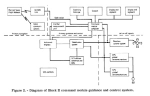
The Guidance and Control System consisted of a number of sub-systems for in-flight navigation and guidance.
This article gives a high-level overview of the sub-systems: detailed information use will be on individual pages for those systems.
PGNCS Overview
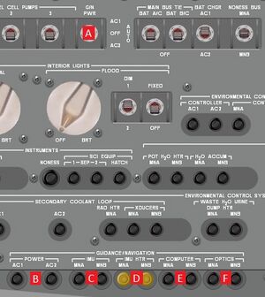
The Primary Guidance, Navigation and Control System (PGNCS) provides the spacecraft with an onboard means of measuring orientation, position, velocity, and trajectory. These values are typically computed by MSFN, uplinked to the spacecraft, and stored for use by the PGNCS. However, in the event of a loss of communications the PGNCS can also serve as the primary mode of guidance. The PGNCS also provides automatic control over parts of the spacecraft via the Command Module Computer (CMC). The GN system can receive power from both AC bus 1 and AC bus 2 by closing the POWER circuit breakers 5.B on MDC-5. The AC bus which the system draws alternating current from is selected by the GN switch 5.A on MDC-5. The sub-systems in the PGNCS use direct current from the main busses, and their means of drawing power is discussed in their sections of this article.
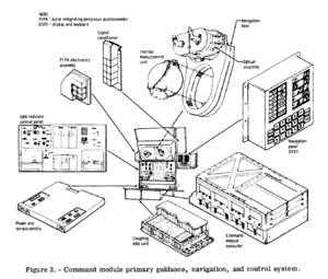
The PGNCS is a tightly interwoven system consisting of three main subsystems: the Inertial Subsystem (ISS), the Computer Subsystem (CSS), and the Optics Subsystem (OSS). The ISS measures information on the spacecraft orientation and velocity by providing a stable platform of reference, the Inertial Measuring Unit (IMU). The CSS applies this information to its current knowledge of the spacecraft's position and calculates a new estimate, what is called the state-vector. The CSS also behaves as an integrated auto-pilot. The OSS consists of a sextant and telescope that allows the crew to take navigation sightings to aid the CSS in properly aligning the IMU. The CSS can also manipulate the optics pieces to point at specific point of interest, based upon its understanding of where it is in relation to the universe.
CDUs
The Coupling Data Units (CDUs) allow the ISS and OSS systems to interface with the computer. These electronic devices convert the analog signals of the IMU and optics into digital signals to be read by the CMC. They also convert digital commands from the computer to analog signals in order for the computer to command the movement of IMU gimbal motors and OSS optics. The OSS CDU also allows for digital-to-analog conversion of the SPS gimbal angles during thrust vector control maneuvers.
Inertial Subsystem

The ISS contains a Navigation Base, Inertial Measurement Unit, and three Coupling Data Units. The navigation base houses and mounts the IMU and optics. The primary purpose for the ISS is to provide the spacecraft with a stable platform of reference. Unlike a typical orbiter spacecraft, which automatically uses the body that it is influenced by for attitude reference, the Apollo spacecraft uses a fixed point against the starts. Different points maybe chosen depending on the requirements of the mission. These points are referred to as the reference to a stable member matrix (REFSMMAT). There are a number of different REFSMMATs during a mission.
The Inertial Measurement Unit (IMU) is the stable member for the ISS. It is a solid block of beryllium with holes bored into its structure to support gyros and accelerometers. The three inertial rate integrating gyros (IRIGs) measure the spacecrafts rotations and keep the IMU stable in respect to the current REFSMMAT. The IRIGs recognize any attitude errors as a result of spacecraft rotation and generate error signals which are interpreted by stabilization loop electronics. These electronics command the IMU's gimbal torque motors to reposition the IMU to the proper attitude.
The IMU also contains three pulse integrated pendulous accelerometers (PIPAs), which measure the spacecraft's acceleration. When acceleration or deceleration is detected by one or several PIPAs, a pulse train is sent to the CMC, allowing it to take the acceleration into account in its state vector. In response, the CMC updates its velocity information, and torques the PIPAs back to null.
The IMU's temperature is controlled through normal convection when it is in stand-by mode. Under normal operating conditions, heaters provide heat to the IMU, IRIGs, and PIPAs when it is necessary. Also, blower controller cooling and water-glycol coolant prevent the IMU from over-heating.
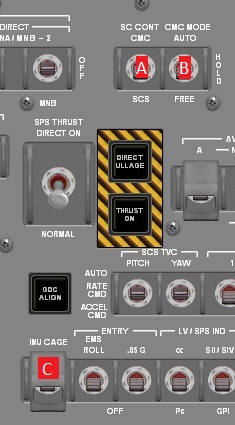
The ISS receives current from either main bus by closing the two IMU circuit breakers 5.C on MDC-5. The IMU HTR circuit breakers 5.D supply current from the main busses to the IMU heaters. The guarded IMU switch 100.B on LEB-100 turns the IMU on. After the IMU is activated during pre-launch, it must be aligned to the launch REFSMMAT by using Program 01. If the IMU is reactivated during flight due to a malfunction, it must be realigned to the stars. The IMU CAGE switch 1.C on MDC-1 will use spacecraft power to "cage" the IMU, or lock all three axis at 0 degrees. Uncaging the IMU will turn off the power caging the IMU, but the IMU will not return to its previous platform.
In a weight saving maneuver, engineers included only three gimbals on the IMU. The Gemini spacecraft included four, which made the platform heavier. The three gimbal setup of Apollo was both lighter, and had a less dramatic drift. Over time, errors in a stable platform will cause a small drift in the current attitude. The errors are miniscule, but must be correct for using the optics, as even small errors can prove catastrophic during powered flight. This process of correcting for errors is known as an IMU realign. There are both coarse and fine IMU realigns that may be called for in the flight plan. The three gimbal setup did have an unfortunate side-effect however, known as gimbal lock.
If the IMU gimbals are driven in a certain manner, they will line up. When they are lined up, the stabilization loop electronics can no longer tell which motor needs to be driven to stabilize the platform, and the IMU locks. Similar to caging the IMU, the platform will stop, and this can be detected by the GIMBAL LOCK light, and the fact that the FDAI will stop operating. On the FDAI, a red circle at both 90 and 270 degrees yaw at 0 degrees pitch indicates where the IMU is in danger of gimbal lock. This area of the FDAI must be taken into account during all maneuvers, as coming out of gimbal lock is a time consuming procedure. To fix gimbal lock, the IMU must be caged and uncaged, zeroing it. Then the spacecraft is manually pointed in the general direction of prograde. Finally, a coarse IMU realign using the COAS is performed.
Computer Subsystem
The Command Module Computer is often compared to modern general purpose computers in the fact that it has far less memory and operating power. This comes from the misunderstanding of the CMC as a general purpose computer with the ability to act as a control computer. In actuality it was a control computer with the ability to act as a general purpose computer. The functions of the CMC are extremely narrowly defined. It will not allow you to use it as a calculator, or open up a word document, or play solitaire. But what it does do it does extremely well. And that is to calculate the current state vector and calculate spacecraft maneuvers. A better comparison would be to compare the CMC to your GPS, rather than to your desktop computer.
The computer draws power from the either Main Bus A or B, and the COMPUTER circuit breakers 5.E supply DC current to the computer. The CSS consists only of the CMC and its means of interface with the crew, the display and keyboard (DSKY). Interaction between the astronauts and the AGC was primarily through the Display and Keyboard Assembly interface which allowed the AGC to display information and the astronauts to enter new values. There is one DSKY on MDC-2 and a second in the lower equipment bay. Both DSKYs serve the same purpose and are not capable of operating separately. The CMC has seven different blocks: the timer, the sequence processer, the central processer, memory, priority control, the input and output channels, and the power.
Timer - The timer provides synchronized pulses to help organize the flow of data in the CMC. It also provides timing waveforms for the CMC alarm circuitry as well as timing and synchronization in the spacecraft. The timer controls the CMC clock.
Sequence Generator - The sequence generator logically sequences the CMC's instructions by a series of control pulses that sequence data within the computer. An order code processor passes the machine's commands and stores and orders commands coming into the computer. It passes these commands to a command generator which creates instruction commands for the control pulse generator.
Central Processor - The central processor is the hub of the CMC, as it carries out, in sequence, all the arithmetic required from the computer at any given time. The computer performs these calculation by temporarily storing some information onto internal registers. These registers include the results of operations, the computer's present step in a calculation, and the location of any data needed to be recalled from memory.
The central processor also monitors data that coming in and out of the CMC's memory. Parity bits are generated by the central processor for anything being written into memory. When data is recalled from the computer's memory, the central processor also "proofreads" its previous writing.
Memory - There are two types of memory in the CMC: fixed and erasable. Fixed memory includes items like program instructions. Erasable memory is memory which the computer or the astronaut may overwrite. This includes things like the mission's pad load (or set of guidance variables that are loaded while still on the ground), or the state vector.
Priority Control - The priority control initiates tasks that update counters within the CMC erasable memory. Also, the computer is capable of stopping the sequence if something more important arises. The interrupt priority control will insert important tasks into the sequence as the need arises. Input-Output Channels - The CMC contains a number of input and output channel that allows into to interface with and control other parts of the spacecraft. An output to another spacecraft component will fall into one of three categories: data, control, or condition indication. Inputs come from the spacecraft's hardware, such as the IMU, or from the astronaut. For example: data from the DSKYs or the MARK button are inputs.
Power - A 28-volt DC source voltage is supplied by the fuel cells. The power is passed through the control module which regulates the proper voltage necessary for use by the CMC.
The CMC is capable of controlling the command module's attitude by using the RCS Digital Autopilot (DAP) and the TVC Digital Autopilot. The RCS DAP provides rotational control during unpowered flight using the Reation Control System. During powered flight, the SPS gimbal provides for control of CSM pitch and yaw, and roll is still controlled by the RCS.
To control the spacecraft using the RCS DAP, it first must be under CMC control. The SC CONT switch 1.A on MDC-1 toggles between whether the SCS or CMC has control of the spacecraft. The adjacent CMC MODE switch 1.B determines which mode of operation the RCS DAP is in. When set to FREE, the RCS DAP interprets all RHC inputs as acceleration commands. When there are no inputs from the RHC, the CSM will drift freely. In HOLD mode, the DAP attempts to hold the attitude that the spacecraft is in. Rotational commands will shift the hold attitude. Hold mode is similar to the SCS's rate command mode. The AUTO mode is similar to HOLD mode, accept the computer can give the DAP an exact target to be maneuvered to. Auto mode is ideal for any precise automatic maneuvers, such as orienting the spacecraft for delta-V maneuvers. If the user sends any inputs to the DAP via the RHC, automatic maneuvers cease and the DAP again behaves as if it is in HOLD mode.
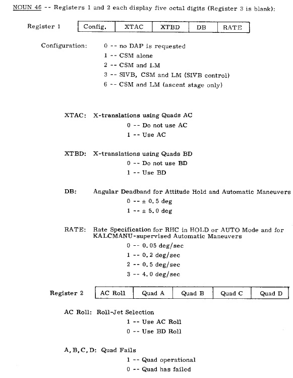
The RCS DAP operates off of a number of variables. Enter Verb 48 will display a sequence of three Nouns (46-48) which configure the DAP. Noun 46 contains two registers. Both registers are octal and neither register is one value. Each digit informs the computer of a different variable for the Digital Autopilot.
Note that the CMC will take into account any quads that have failed. The following Noun, 47, contains two decimal values. Register one is the current mass of the CSM, and register two is the current mass of the LM. Both values must be entered by the user in pounds. The final Noun 47 contains two more decimal registers for the SPS pitch gimbal offset, and than the SPS yaw gimbal offset. Both of these values are for use by the TVC DAP. Keying in Verb 46 will activate the Digital Autopilot.
Optics Subsystem
The OSS contains a sextant (SXT) and scanning telescope (SCT), controls and displays in the lower equipment bay, and two CDUs. The OSS is also affixed to the navigation base. It is used to take navigation sightings of stars and landmarks to help the computer refine the current state vector and realign the platform. The SXT and SCT can also be manipulated by the computer to point at landmarks and stars, as well as track a landmark as the CSM passes overhead in orbit. The scanning telescope is slaved to the sextant, meaning they are pointed at the same target. The sextant has 28x magnification and a 1.8 degree FOV. It can take sighting within a 50 degree arc. The scanning telescope allows for a 60 degree field of view at 1x magnification, and serves the purpose of providing a broad overview of the sextants target, to allow the astronaut to orient himself.
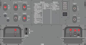
The OSS receives power from either main bus via the OPTICS circuit breakers 5.F on MDC-5. The OPTICS switch 100.A on LEB-100 activates the optics. The rest of the optics controls are on the optics panel, LEB-121 and 122, which dominate the lower equipment bay. The MODE switch 122.A determines whether the optics are controlled by the astronaut or the computer, or whether the optics are automatically reset. When it is set to MANUAL, the optics are maneuvered via the thumb switch on the lower right 122.F or the WASD keys on the keyboard. When set to CMC, the switch hands control off to the computer to allow the optics to be automatically aimed. Finally, ZERO will automatically center the optics. Zeroing of the optics must be done before initiating any computer programs that make use of the optics. The speed of the manual optics movements is set by the SPEED 122.B switch. The COUPLING switch 122.C determines whether the astronaut's inputs are resolved into X/Y image translations, when set to RESOLVE, or are direct commands to the shaft and trunnions, when set to DIRECT. The TELESCOPE TRUNNION switch 122.D determines whether the telescope is slaved to the sextant's target, always zeroed, or offset from the sextant by 25 degrees up.
The thumb switch 122.E on the lower left of panel LEB-122 provides for minimum impulse (a single burst from a single RCS thrusters, as opposed to the typical pair) rotational control to steady the spacecraft when taking navigation sightings, or to aim the sextant during cislunar navigation Program 23. Alternatively, the user may use SHIFT-WASDQE to control rotation. The spacecraft must be under CMC FREE mode for this switch to operate. When the computer requests the user to make a mark on a specific star the user depresses the MARK pushbutton 122.G after the sextant is centered over the target. The Q key on the keyboard also serves as a mark button. The MARK REJECT pushbutton 122.H tells the computer to erase the previous mark, in the event of an inadvertent mark.
Power Servo Assembly
The Power Servo Assembly (PSA) supplies AC and DC voltage to the sub-systems in the PGNCS. Power from AC bus 1 or AC bus 2 is supplied to the dimmer controls and anything in the PGNCS that requires lighting, such as the optics warning lights and DSKYs. The IMU and Optics are powered with DC voltage when their appropriate switches on LEB-100 are set to the on position.
See Also
Stabilisation and Control System (SCS)
 |{{#if:|, | and }}[[{{{2}}}|{{{2}}}]]}}{{#if:
 |{{#if:|, |, and }}[[{{{3}}}|{{{3}}}]]}}{{#if:
 |{{#if:|, |, and }}[[{{{4}}}|{{{4}}}]]}}{{#if:
|, and [[{{{5}}}|{{{5}}}]]}}{{#if: | (too many parameters in {{mainarticle}})}}
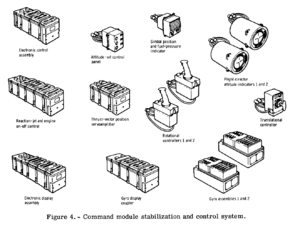
The Stabilization and Control System (SCS) provides a capability for monitoring and controlling the attitude of the spacecraft, for translational manoeuvers and SPS thrust vector control. Also the SCS is the backup system for the Primary Guidance, Navigation and Control System (PGNCS).
Orbital Rate Display Earth And Lunar
 |{{#if:|, | and }}[[{{{2}}}|{{{2}}}]]}}{{#if:
 |{{#if:|, |, and }}[[{{{3}}}|{{{3}}}]]}}{{#if:
 |{{#if:|, |, and }}[[{{{4}}}|{{{4}}}]]}}{{#if:
|, and [[{{{5}}}|{{{5}}}]]}}{{#if: | (too many parameters in {{mainarticle}})}}
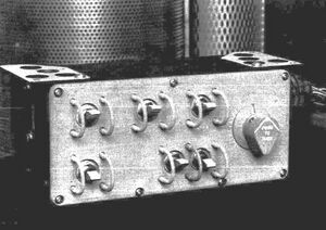
In normal use the Flight Director Attitude Indicator displays would show the inertial attitude relative to distant stars. This was useful in free space, but when in orbit the pilot may want to see the spacecraft's attitude relative to the surface of the Earth or Moon.
The Orbital Rate Display Earth And Lunar (ORDEAL) was a simple system which could be configured to rotate the FDAIs appropriately so that they would display the attitude relative to the surface instead. Configuration is also simple, with a switch for Earth or Moon and an altitude selector, and the orbital rates are calculated automatically from these settings.
Entry Monitoring System
 |{{#if:|, | and }}[[{{{2}}}|{{{2}}}]]}}{{#if:
 |{{#if:|, |, and }}[[{{{3}}}|{{{3}}}]]}}{{#if:
 |{{#if:|, |, and }}[[{{{4}}}|{{{4}}}]]}}{{#if:
|, and [[{{{5}}}|{{{5}}}]]}}{{#if: | (too many parameters in {{mainarticle}})}}
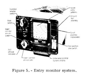
The Entry Monitoring System is used by the crew to monitor the entry trajectory flown by the PGNCS and allows the pilot to fly a manual re-entry if required.
The main EMS panel includes a velocity/load-factor display, range-to-go display, 0.05g indicator and roll/attitude indicator.
External Links
- Apollo experience report: Command and service module reaction control systems
- Apollo experience report: Guidance and control systems
- Apollo experience report: Guidance and control systems - Digital autopilot design development
- Apollo experience report: Lunar module landing radar and rendezvous radar
- Apollo experience report: Lunar module reaction control system
- Apollo Training: Guidance and Control Systems
