Panel Controls and Displays (CSM)
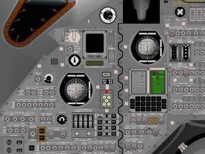
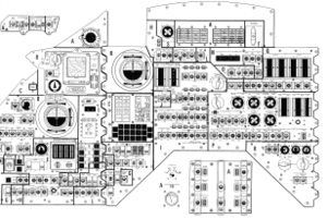
Most of the CSM Panel Controls and Displays are simulated as completely authentic, almost photo realistic 2D panels. Many of the controls and displays are not only "switchable" but are really doing what the original switches did. So you can operate the spacecraft as the real astronauts did.
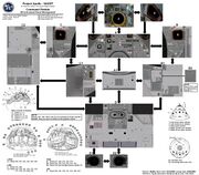
The numerous panels of the real CSM are distributed over several Orbiter panels. To navigate between these panels, the <CTRL> <UP/DOWN/LEFT/RIGHT> key combination is used as in any other Orbiter spacecraft and as explained in the Orbiter manual. The navigation between the panels is shown in the diagram to the right.
Panel Documentation
The CSM panels have a few hundred controls and displays. In the past we tried to provide reference documentation of each single switch and each gauge. The latest version of the old CSM panel reference demonstrates this approach. But the more the panels get realistic it turned out in just copying the original NASA documentation, mainly of the Apollo Operations HandbookAOH controls & displays section, so we suggest to use the original documentation directly for reference purpose.
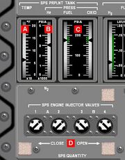
Meanwhile the displays and controls are described in the documentation of their subsystem, so for example the SPS displays and controls are explained in the Service Propulsion System article etc. Screenshots of the panels together with labeled switches are provided as shown in the example to the right. The displays and controls are referenced in the description with a red label showing the panel number and the display or control letter like this:
"The fuel and oxidizer tank pressures are shown by the SPS PRPLNT PRESS meters 3.C."
Apollo Operations Handbook
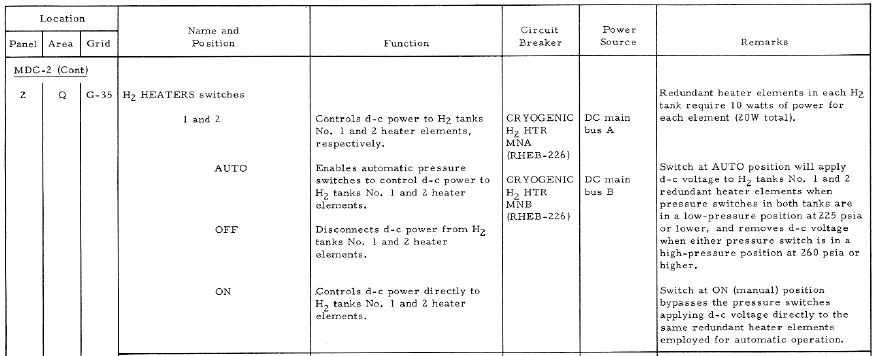
The Apollo Operations Handbook controls & displays section is a reference of each switch and each display on the Project Apollo panels. Controls and displays are presented in form of a tabulated list in numerical order by panel and area number. The following is a detailed explanation of the columnar data presented in the tabulated lists:
| Name | Given the exact nomenclature of a particular control or display. The name of the switch or control in the C++ code should be similar like shown in the following example: The name of the CABIN FAN switches in the code are CabinFan1Switch and CabinFan2Switch. |
| Panel Locator | The panel locator provides the "coordinates" of the display or control. You can download the panel locator figures from the Apollo Operations Handbook separately. Firstly there is the panel number, larger panels are further divided into areas. In most instances, the area correlates to a specific spacecraft system. Panels 1 through 16 have grid reference numerical marks horizontally and alphabetic marks vertically on the drawing. |
| Function | Describes the function of the switch or display. |
| Remarks | Any useful comment. Please notice especially differences to the original function, bugs or other issues. |
Example
Here is an example explaining the H2 HEATERS switches:
Abbreviations
The following abbreviations are used:
lt - light
sw - switch
sel - rotary type switch
cb - circuit breaker
tb - talkback indicator
bp - "barber pole" (striped line indication of a talkback indicator)
vlv - valve
ind - indicator
pb - pushbutton
cont - potentiometer or rheostat
tw - thumbwheel
Additionally to use the DSKY the following abbreviations are used: V is short for VERB, N is short for NOUN, and E is short for ENTR.
<biblio force=false>
</biblio>
