Template:Prelaunch checklist: Difference between revisions
imported>Tschachim No edit summary |
imported>Tschachim (CMC alarm in VAGC mode) |
||
| (9 intermediate revisions by the same user not shown) | |||
| Line 33: | Line 33: | ||
<td rowspan="2" valign="top">-03:00:00</td> | <td rowspan="2" valign="top">-03:00:00</td> | ||
<td valign="top"> | <td valign="top"> | ||
<table class="wikiembeddedtable"> | <table width="100%" class="wikiembeddedtable"> | ||
<tr> | <tr> | ||
<td colspan="2"><em>C/W system activation</em></td> | <td colspan="2"><em>C/W system activation</em></td> | ||
</tr> | </tr> | ||
<tr> | <tr> | ||
<td width="20%"> </td> | <td width="20%"> </td> | ||
| Line 46: | Line 45: | ||
</tr> | </tr> | ||
<tr> | <tr> | ||
<td> </td> | <td> </td> | ||
<td>MASTER ALARM pb/lt (3) - on, </td> | <td>MASTER ALARM pb/lt (3) - on, </td> | ||
| Line 79: | Line 77: | ||
<br> | <br> | ||
<br> | <br> | ||
The suit compressor alarm is normal.</p></td> | {{ #if: {{{VirtualAGC|}}} |The CMC and suit compressor alarms are normal. |The suit compressor alarm is normal. }} </p></td> | ||
</tr> | </tr> | ||
<tr> | <tr> | ||
<td valign="top"><table class="wikiembeddedtable"> | <td valign="top"><table width="100%" class="wikiembeddedtable"> | ||
<tr> | <tr> | ||
<td | <td colspan="2"><em>CMC power up </em></td> | ||
</tr> | </tr> | ||
<tr> | <tr> | ||
<td> </td> | <td width="20%"> </td> | ||
<td width="80%"> </td> | |||
</tr> | </tr> | ||
<tr> | <tr> | ||
<td>cb G/N COMPUTER MNA - close </td> | <td colspan="2">cb G/N COMPUTER MNA - close </td> | ||
</tr> | </tr> | ||
<tr> | <tr> | ||
<td colspan="2">cb G/N COMPUTER MNB - close </td> | |||
<td>cb G/N COMPUTER MNB - close </td> | |||
</tr> | </tr> | ||
<tr> | |||
<td> </td> | |||
<td>{{ #if: {{{VirtualAGC|}}} |CMC lt - out | }} </td> | |||
</tr> | |||
</table></td> | </table></td> | ||
<td valign="top"><table width="100%" class="wikiembeddedtable"> | <td valign="top"><table width="100%" class="wikiembeddedtable"> | ||
| Line 278: | Line 279: | ||
</tr> | </tr> | ||
<tr> | <tr> | ||
<td width=" | <td width="20%"> </td> | ||
<td width=" | <td width="80%">{{ #if: {{{VirtualAGC|}}} |NO ATT lt - on (90 sec) |NO ATT lt - off }}</td> | ||
</tr> | </tr> | ||
<tr> | <tr> | ||
| Line 1,106: | Line 1,107: | ||
<table width="100%" class="wikitable"> | <table width="100%" class="wikitable"> | ||
<tr> | <tr> | ||
<th width=" | <th width="10%" scope="col">Time</th> | ||
<th width="43%" scope="col">Procedure</th> | <th width="43%" scope="col">Procedure</th> | ||
<th width="5%" scope="col"><div align="center">Panel</div></th> | <th width="5%" scope="col"><div align="center">Panel</div></th> | ||
<th width=" | <th width="42%" scope="col">Remarks</th> | ||
</tr> | </tr> | ||
<tr> | <tr> | ||
| Line 1,224: | Line 1,225: | ||
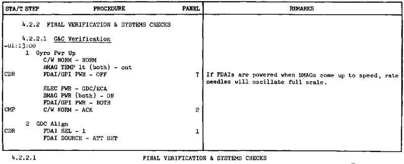
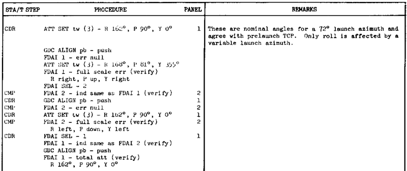
=== G&C verification === | === G&C verification === | ||
The CSM has 2 independent devices, which provide an inertial attitude reference, the IMU and the GDC by using the BMAGs. The IMU was aligned by P01/P02, now the GDC is aligned. The [[CSM FDAI|FDAI]] and [[ | The CSM has 2 independent devices, which provide an inertial attitude reference, the IMU and the GDC by using the BMAGs. The IMU was aligned by P01/P02, now the GDC is aligned. The [[CSM FDAI|FDAI]] and [[ASCP]] articles explain the displays and controls, which are used for that. The GDC ALIGN pushbutton stores the attitude currently set in the ASCP in the GDC, so with that you can change the GDC attitude manually and this is done in the following. | ||
[[Image:Checklist_prelaunch_finalchecks1.gif]] | [[Image:Checklist_prelaunch_finalchecks1.gif]] | ||
| Line 1,320: | Line 1,321: | ||
<table width="100%" class="wikitable"> | <table width="100%" class="wikitable"> | ||
<tr> | <tr> | ||
<th width=" | <th width="10%" scope="col">Time</th> | ||
<th width="43%" scope="col">Procedure</th> | <th width="43%" scope="col">Procedure</th> | ||
<th width="5%" scope="col"><div align="center">Panel</div></th> | <th width="5%" scope="col"><div align="center">Panel</div></th> | ||
<th width=" | <th width="42%" scope="col">Remarks</th> | ||
</tr> | </tr> | ||
<tr> | <tr> | ||
| Line 1,398: | Line 1,399: | ||
</table> | </table> | ||
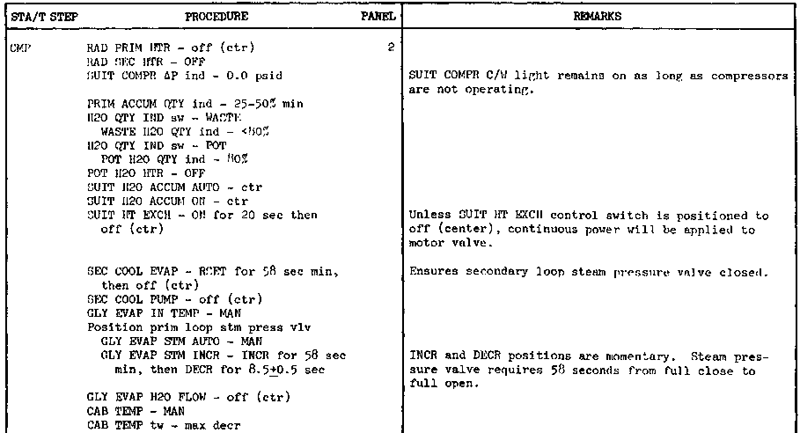
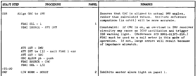
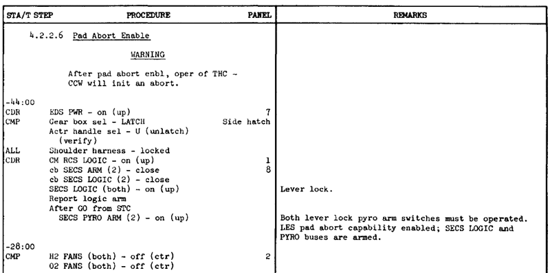
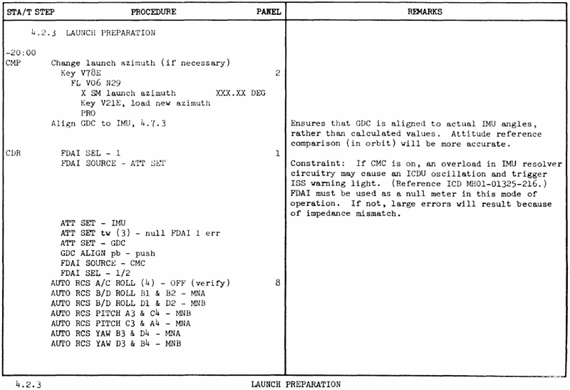
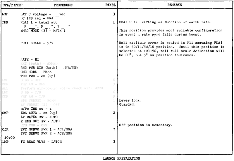
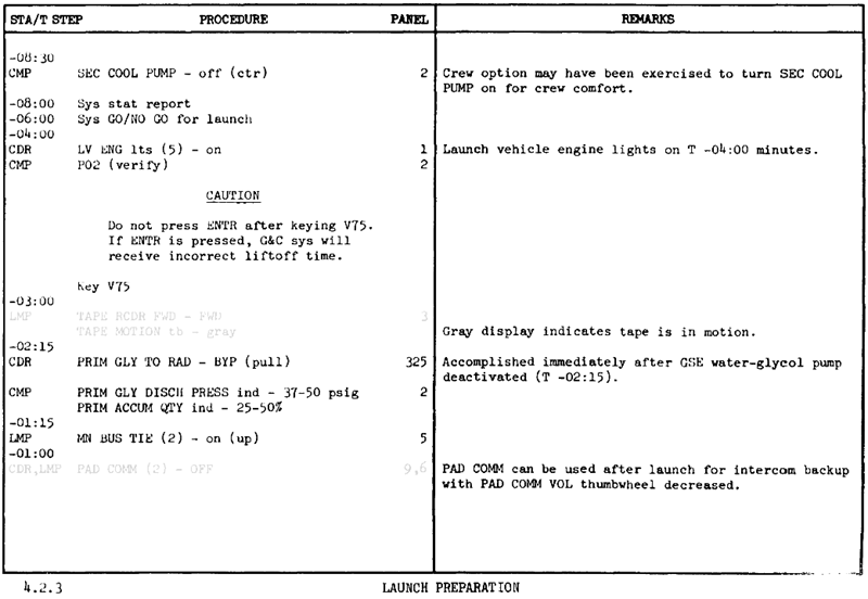
== Launch preparation == | |||
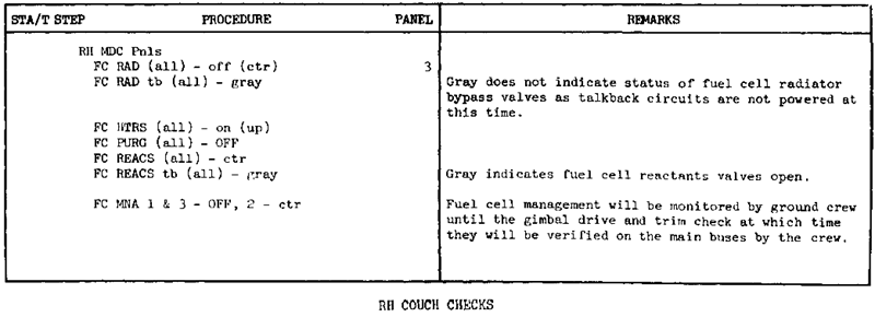
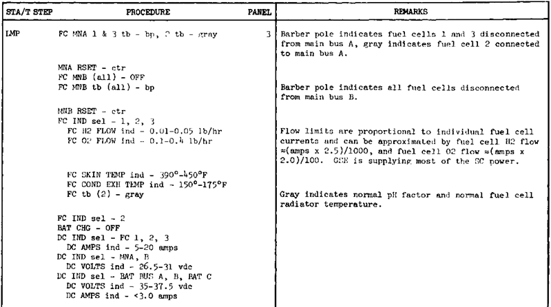
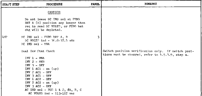
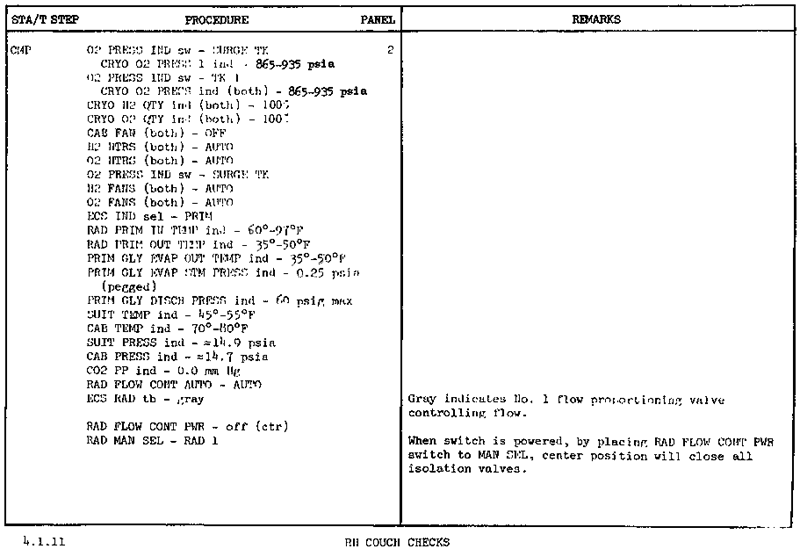
These are the last checklist actions before lift-off. | |||
{{ #if: {{{VirtualAGC|}}} | | {{Attention | message=Please note that all DSKY interaction mentioned in the original documentation cannot be used in ''Standard mode'' with the [[Simple AGC]]. }} | |||
}} | |||
[[Image:Checklist_prelaunch_launchpreparation1.gif]] | |||
[[Image:Checklist_prelaunch_launchpreparation2.gif]] | |||
[[Image:Checklist_prelaunch_launchpreparation3.gif]] | |||
[[Image:Checklist_prelaunch_launchpreparation4.gif]] | |||
<biblio force=false> | <biblio force=false> | ||
#[[References]] | #[[References]] | ||
</biblio> | </biblio> | ||
Latest revision as of 18:06, 28 January 2007
When it's possible, the original Apollo documentation is used for the checklists. Steps, which are not possible at the moment, are denoted in grey. Additionally there are checklists in Word file format in the Doc\Project Apollo - NASSP\Check List directory of your installation. Procedural steps in this section are presented in tabular form and in sequence they occure during the mission. The following is a detailed explanation of the columnar data presented in the tabulated lists:
| Time | This column contains the mission time the procedure is to be done. Sometimes there's no fixed time when to do a procedure, in that case the time is left out. |
| Procedure | The procedure is a group of steps or overall tasks involved in performing a complete function or operation. It often consists of controls the astronauts have to toggle or display readings that have to be checked. See CSM panels for more informations. |
| Panel | The panel number of a particular switch or display for easier panel navigation. |
| Remarks | Any useful comment. Please notice especially differences to the original function, bugs or other issues. |
Spacecraft systems activation
In Project Apollo - NASSP the Saturn prelaunch checklist starts at 3 hours before launch with the backup crew in the spacecraft. At first some of the spacecraft's systems have to be activated.
| Time | Procedure | Panel |
Remarks | |||||||||||||||
|---|---|---|---|---|---|---|---|---|---|---|---|---|---|---|---|---|---|---|
| -03:00:00 |
|
|
|
|||||||||||||||
|
|
Activation of the command module computer. |
||||||||||||||||
{{ #if: |
|
|
Run program P00
|
||||||||||||||||||||||||||||||
|
|
|
Light test isn't historically correct.
(not historically correct). |
||||||||||||||||||||
}}
|
|
Activation of the inertial |
|||||||||||||||||||||||||||
Backup crew prelaunch checks
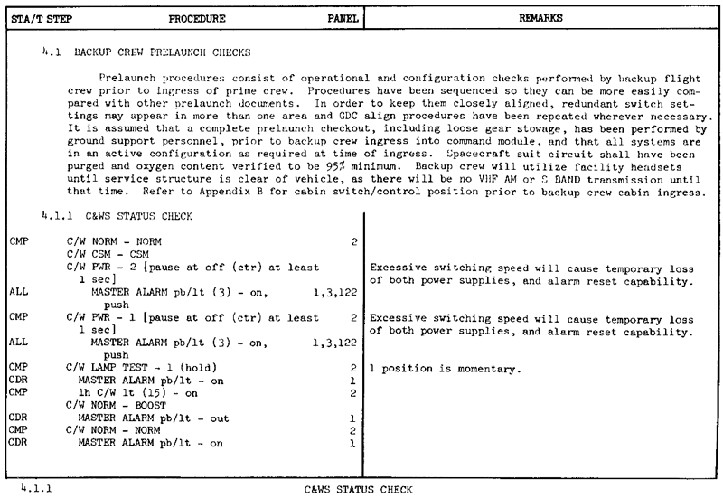
C&WS status check
With the first procedure the caution and warning system is checkedAOH2.
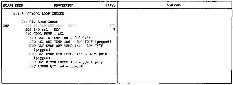
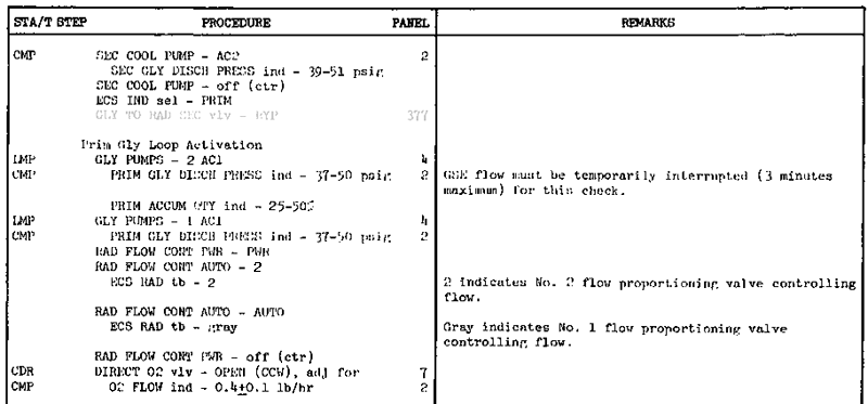
Glycol loop checks
Next the primary and secondary water-glycol coolant loops are checked and the primary water-glycol coolant loop is activated. The grey lines indicate displays or controls which are not available at the moment, please ignore these steps.
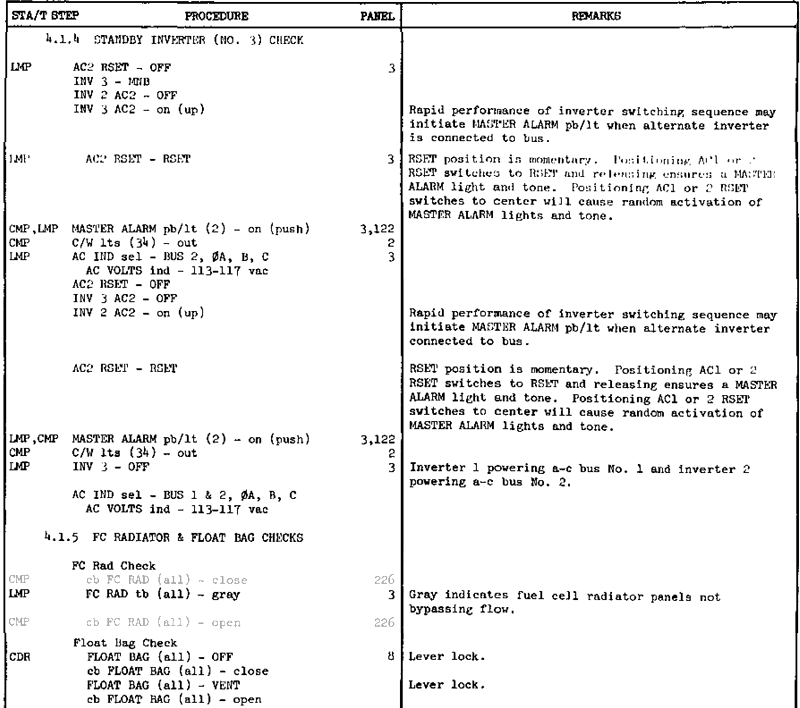
Standby inverter checks
| Time | Procedure | Panel | Remarks |
|---|---|---|---|
| C/W NORM - BOOST | 2 | This is not mentioned in the Apollo Operations HandbookAOH2, but otherwise the C/W lights during the inverter check won't work. |
Panels checks
Next some checks regarding the panel displays and controls have to be done and a few but very important devices have to be turned on. We begin at panel 325, which is to the left of the left side panel.
| Time | Procedure | Panel |
Remarks | |||||||||||||||||||||||||||||||||||||||||||||||||||||
|---|---|---|---|---|---|---|---|---|---|---|---|---|---|---|---|---|---|---|---|---|---|---|---|---|---|---|---|---|---|---|---|---|---|---|---|---|---|---|---|---|---|---|---|---|---|---|---|---|---|---|---|---|---|---|---|---|
|
|
|||||||||||||||||||||||||||||||||||||||||||||||||||||||
|
|
|||||||||||||||||||||||||||||||||||||||||||||||||||||||
|
|
|
||||||||||||||||||||||||||||||||||||||||||||||||||||||
|
|
|
||||||||||||||||||||||||||||||||||||||||||||||||||||||
|
|
|
||||||||||||||||||||||||||||||||||||||||||||||||||||||
|
|
|||||||||||||||||||||||||||||||||||||||||||||||||||||||
|
|
|||||||||||||||||||||||||||||||||||||||||||||||||||||||
Prelaunch alignment
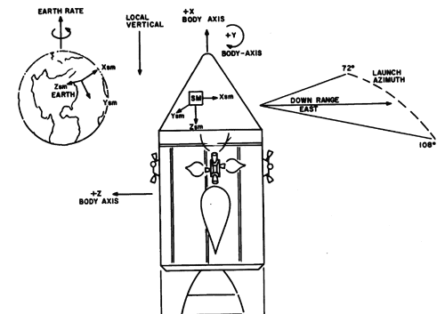
Now the prelaunch programs of the CMC are started, the DSKY is used for that. During prelaunch the IMU platform, also called stable member (SM), is aligned to launch position.
{{ #if:
|
| Time | Procedure | Panel |
Remarks | ||||||||||||||||||||||||
|---|---|---|---|---|---|---|---|---|---|---|---|---|---|---|---|---|---|---|---|---|---|---|---|---|---|---|---|
|
|
After starting P01 "Prelaunch or service initialization program" the IMU changes to course align mode and drives the stable member to prelaunch position.
Then it changes automatically to P02 "Prelaunch or service gyro compassing program". Because the AGC commands during P02 are very small you can't see them at the FDAI, but you can monitor the IMU gimbal angles with V16 N20E. |
|||||||||||||||||||||||||
|
The AGC did a prelaunch alignment for the launch azimuth as it is stored in the scenario. If you like, you can check or change it. This is done with verb 78, the DSKY shows the present launch azimuth. Press PRO to continue without changing, with verb 21 you could "load component 1 into R1" and change the launch azimuth in the format +XXX.XX°. Press PRO to confirm the new setting. Press CLR to clear a wrong input. | ||||||||||||||||||||||||||
|
After pressing PRO the AGC changes the attitude of the stable member with gyro pulses to the new launch azimuth. | ||||||||||||||||||||||||||
|
| Time | Procedure | Panel |
Remarks | ||||||||||||||
|---|---|---|---|---|---|---|---|---|---|---|---|---|---|---|---|---|---|
|
|
Start P01 "Prelaunch or service initialization program". |
|||||||||||||||
|
Verb 06, noun 29 shows the desired launch azimuth in format XXX.XX°, press PRO to confirm. | ||||||||||||||||
|
Noun 44 shows shows in R1 the desired apoapsis and in R2 the periapsis altitude, both in format XXXX.X m, press PRO to confirm. | ||||||||||||||||
|
Noun 33 shows time to lift-off, hours in R1, minutes in R2 and seconds in R3. Verb 16 monitors the countdown, that means the DSKY updates the time every 2 seconds. (not historically correct) | ||||||||||||||||
}} The computer and the IMU are running and ready for launch.
Prime Crew Ingress/Cabin Closeout
Now the spacecraft is ready for prime crew ingress and cabin closeout. In real Apollo prime crew ingress began at T-02:40:00 and ends with closing the hatch at T-01:40:00. In between the prime crew did a lot of checks similar to the backup crew checks above.
In Project Apollo - NASSP as a simplification both events happen simultaneously and take place at T-01:40:00, the prime crew checks are left out. If you use time acceleration the simulation slows down automatically at that time and some audio of the prelaunch is played. Please make sure that you do the following steps directly or shortly after T-01:40:00.
| Time | Procedure | Panel |
Remarks | |||||||||||||||||||||||||||||||||||
|---|---|---|---|---|---|---|---|---|---|---|---|---|---|---|---|---|---|---|---|---|---|---|---|---|---|---|---|---|---|---|---|---|---|---|---|---|---|---|
| -01:40:00 |
|
|
|
|||||||||||||||||||||||||||||||||||
Final verification & system checks
Now the prime crew continues with the final system checks before launch. At the beginning the BMAGs (Body Mounted Attitude Gyro) are turned on, the FDAIs and the GDC (Gyro Display Coupler) are checked and the GDC is aligned to the reference attitude for a typical launch azimuth.
G&C verification
The CSM has 2 independent devices, which provide an inertial attitude reference, the IMU and the GDC by using the BMAGs. The IMU was aligned by P01/P02, now the GDC is aligned. The FDAI and ASCP articles explain the displays and controls, which are used for that. The GDC ALIGN pushbutton stores the attitude currently set in the ASCP in the GDC, so with that you can change the GDC attitude manually and this is done in the following.
Main bus activation
Now the main bus supply is configured for flight. During prelaunch and up to now the main bus power is supplied by the GSE (Ground Support Equipment), only Fuel Cell 2 is connected with Main Bus A. GSE is disconnected at T-15 min, so we have to power both buses with the fuel cells before that.
| Time | Procedure | Panel |
Remarks | ||||||||||||||||||
|---|---|---|---|---|---|---|---|---|---|---|---|---|---|---|---|---|---|---|---|---|---|
|
|
|
|||||||||||||||||||
FDAI verification
Next the FDAIs are set in flight configuration, the GDC attitude is aligned to the IMU attitude.
Pad abort enable
Now the pyros and sequential systems are armed.
SM RCS activation
Last the SM RCS is activated, please note that most of the RCS displays and controls are not working yet.
| Time | Procedure | Panel |
Remarks | |||||||||||||||||||||||||||
|---|---|---|---|---|---|---|---|---|---|---|---|---|---|---|---|---|---|---|---|---|---|---|---|---|---|---|---|---|---|---|
| -00:25:00 |
|
|
||||||||||||||||||||||||||||
Launch preparation
These are the last checklist actions before lift-off. {{ #if: | |
| ||
| Please note that all DSKY interaction mentioned in the original documentation cannot be used in Standard mode with the Simple AGC. |
<biblio force=false>
</biblio>
