Entry Monitoring System

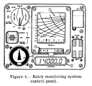
The Entry Monitoring System (EMS) provides a visual monitor of automatic Primary Guidance and Control System (PGNCS) entries and delta velocity manoevers. The EMS also provides sufficient display data to permit manual entries in the event of PGNCS malfunctions together with a command sent to the SCS for SPS engine cutoff. The delta velocity display can also be used as the cue to initiate manual thrust-off commands if the automatic-off commands malfunction. During rendezvous the EMS provides a display of VHF ranging information.
Self-test provisions are provided by a function switch for three operational modes (entry, ΔV and VHF ranging) to provide maximum system confidence prior to actual use.
When the EMS FUNCTION switch is switched to OFF position, the EMS is turned off except the SPS THRUST light and the roll stability indicator, in any other position it's turned onI. When turned on and the EMS MODE switch is switched to STBY (standby mode), it's powered and the set functions are working, but system operation is inhibited, that means the EMS doesn't receive data from the accelerometer for example.
Entry Functions
Prior to discussing the individual components and their functions, there are a few things that need to be known about reentry in the Apollo Spacecraft. The first is the event known as Entry Interface. Entry Interface occurred after which point the Command Module is considered to be reentering the Earth's atmosphere. On Trans-Lunar trajectories, this event was given the somewhat arbitrary definition of being when the capsule passed 400,000 feet above the Earth's surface.
EMS Scroll
The part of the EMS that visually stands out the most is the EMS Scroll. Its purpose was simple. Provide a visual aid by which one could monitor an automatic reentry and fly a manual reentry if needed. It consisted of a mylar scroll backed with an emulsion that would be scratched away by a needle behind the display. The resulting trace would then be visible to the astronauts. Using values radioed up from ground stations or on-board computer calculations, the astronauts would preset the scroll to the projected velocity at which the
.05G (Threshold) Indicator
Most of the entry functions of the EMS centered around this "Entry Threshold" concept. The .05G Indicator was activated by the accelerometer reading the initial deceleration due to atmospheric sources. Typically on Trans-Lunar flights, this occurred approximately 30 seconds after Entry Interface. Once the .05G Indicator was tripped, a series of events were set in motion. This Indicator was responsible for starting the EMS Scroll's motion, as well as beginning calculations related to Corridor verification.
Roll Stability Indicator
The Roll Stability Indicator (RSI) provided an indication of which direction the lift vector was pointed during entry.
Corridor Verification Indicators
Bordering the Roll Stability Indicator on the top and bottom are the Corridor Verification Indicators. These two lights were the astronauts first visual signal of how accurate their reentry angle was and which direction to point their lift vector. About 10 seconds after the .05G indicator was illuminated, a test was done to determine if the reentry corridor was within desired limits. If the G-level was below .262G's at this time, the Down-light would be lit. If the G-level was above .262G's, the Up-light would be lit. The astronauts would then orient the spacecraft so as to receive the correct lift vector.
ΔV Functions
In addition to the entry functions, the EMS provides outputs related to the delta velocity (ΔV) manoevers during SPS or RCS thrusting along the CSM X-axis (foreward/backward). Both the SPS THRUST light and the ΔV numeric counter display information during a ΔV. In addition, an automatic thrust-off command signal is supplied to the SCS when the ΔV counter reaches zero.
SPS THRUST Indicator
The SPS THRUST indicator will be illuminated any time one of the SPS bipropellant engine injector valves systems A or B are open (powered) regardless which thrust mode is used, see the Service Propulsion System for more details about the different thrust modes. It also works when the EMS is turned off or in standbyII.
ΔV SET mode
Prior to a ΔV manoever or a ΔV test the EMS ΔV/RANGE display needs to be set to the desired velocity change in ft/s.
To enable the ΔV SET mode the EMS FUNCTION switch is switched to ΔV SET/VHF RNG and the EMS MODE switch to NORMAL or STBY. Then, the ΔV/EMS SET switch, a five-position rocker switch, is used to drive the ΔV/RANGE display. Clicking and holding down the left mouse button on the upper/lower part of the switch increases or decreases the display at 127.5 ft/s per second. Clicking and holding down the right mouse button increases or decreases the display at 0.25 ft/s per secondAOH. Minimum readout is -1000 ft/s, maximum is 14000 ft/s.
ΔV mode
After the EMS ΔV/RANGE display is configured with the desired velocity change along the CSM X-axis, the ΔV mode is used to monitor the remaining ΔV and to provide a thrust-off command to the SPS engine during a SCS-controlled burn.
To enable the the ΔV mode the EMS FUNCTION switch is switched to the ΔV position. Then the EMS will measure the acceleration along the CSM X-axis and the EMS ΔV/RANGE display will count up or down according to that with the EMS MODE switch in NORMAL position. The display counts down with the SPS or RCS thrusting along the CSM +X-axis (foreward) or up with RCS thrusting along the CSM -X-axis (backward). The BACKUP/VHF RNG position of the EMS MODE switch permits only a decreasing readout during thrusting. Minimum readout is -1000 ft/s, maximum is 14000 ft/s.
During a SCS-controlled SPS burn when the EMS ΔV/RANGE display decreases to a value of -0.1 ft/s or below, a thrust-off signal is supplied to the SPS engine thrust on/off logic stopping the SPS burn when the desired velocity change is accomplished. Consequently, the THRUST ON pushbutton will not turn on the SPS engine unless the EMS ΔV/RANGE display reads zero or greater.
In order to test the EMS ΔV functions and to simulate 0g (free fall) in the vertical stack configuration of the spacecraft on the ground, the GTA switch is used. With the cover plate removed (right mouse button) and the GTA switch switched to the upper position, an additional test signal is applied to the accelerometer signal, which exactly counteracts Earth's gravity on the ground. This is used on the ground during prelaunch only.
ΔV TEST mode

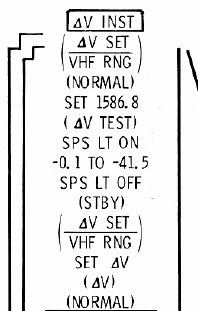
During prelaunch and prior to a SPS burn a self-test of the EMS ΔV functions is performed. This is done with the following procedure, which is also printed on the EMS entry scroll.
- It is assumed that this test is done in weightlessness in space. To perform the test on the ground, the GTA switch has to be uncovered and switched to upper position.
- The ΔV SET mode is enabled by switching the EMS FUNCTION switch to ΔV SET/VHF RNG and the EMS MODE switch to NORMAL.
- The ΔV/EMS SET five-position rocker switch is used to drive the ΔV/RANGE display to 1586.8 ft/s.
- The EMS FUNCTION switch is switched to ΔV TEST. The SPS THRUST light is turned on and the reading of the ΔV/RANGE display begins to decrease.
- When the ΔV reading drops below zero, the SPS THRUST light is turned off. The reading stops to decrease after 10 seconds, the ΔV/RANGE display shows -20.8 +/- 20.7 ft/s.
- The test is complete, the EMS is turned off or switched to standby and the ΔV/RANGE display is set to the next desired velocity change like shown on the EMS ΔV instructions on the entry scroll.
VHF RNG mode
<biblio force=false>
#I The EMS receives power from the EMS MNA/B circuit breakers on panel 8.
#II SPS THRUST indicator receives power from the EMS MNA/B circuit breakers on panel 8 directly.
#References
</biblio>